Answered step by step
Verified Expert Solution
Question
1 Approved Answer
1) Write equations in the Laplace- domain describing the voltage to the left of inductor #1 [ node N] and to the right of

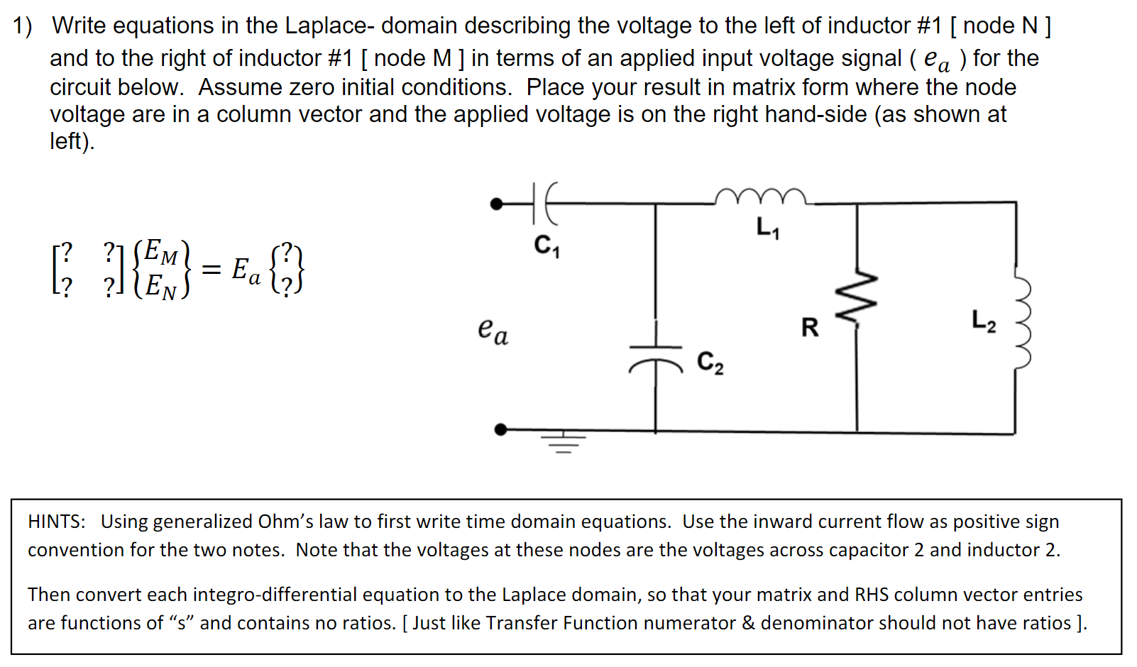
1) Write equations in the Laplace- domain describing the voltage to the left of inductor #1 [ node N] and to the right of inductor #1 [ node M ] in terms of an applied input voltage signal ( ea ) for the circuit below. Assume zero initial conditions. Place your result in matrix form where the node voltage are in a column vector and the applied voltage is on the right hand-side (as shown at left). HE L C [{ }]}]{M} = ?] [EM] L2 N Ea R E ea C HINTS: Using generalized Ohm's law to first write time domain equations. Use the inward current flow as positive sign convention for the two notes. Note that the voltages at these nodes are the voltages across capacitor 2 and inductor 2. Then convert each integro-differential equation to the Laplace domain, so that your matrix and RHS column vector entries are functions of "s" and contains no ratios. [Just like Transfer Function numerator & denominator should not have ratios ].
Step by Step Solution
There are 3 Steps involved in it
Step: 1

Get Instant Access to Expert-Tailored Solutions
See step-by-step solutions with expert insights and AI powered tools for academic success
Step: 2

Step: 3

Ace Your Homework with AI
Get the answers you need in no time with our AI-driven, step-by-step assistance
Get Started


