Answered step by step
Verified Expert Solution
Question
1 Approved Answer
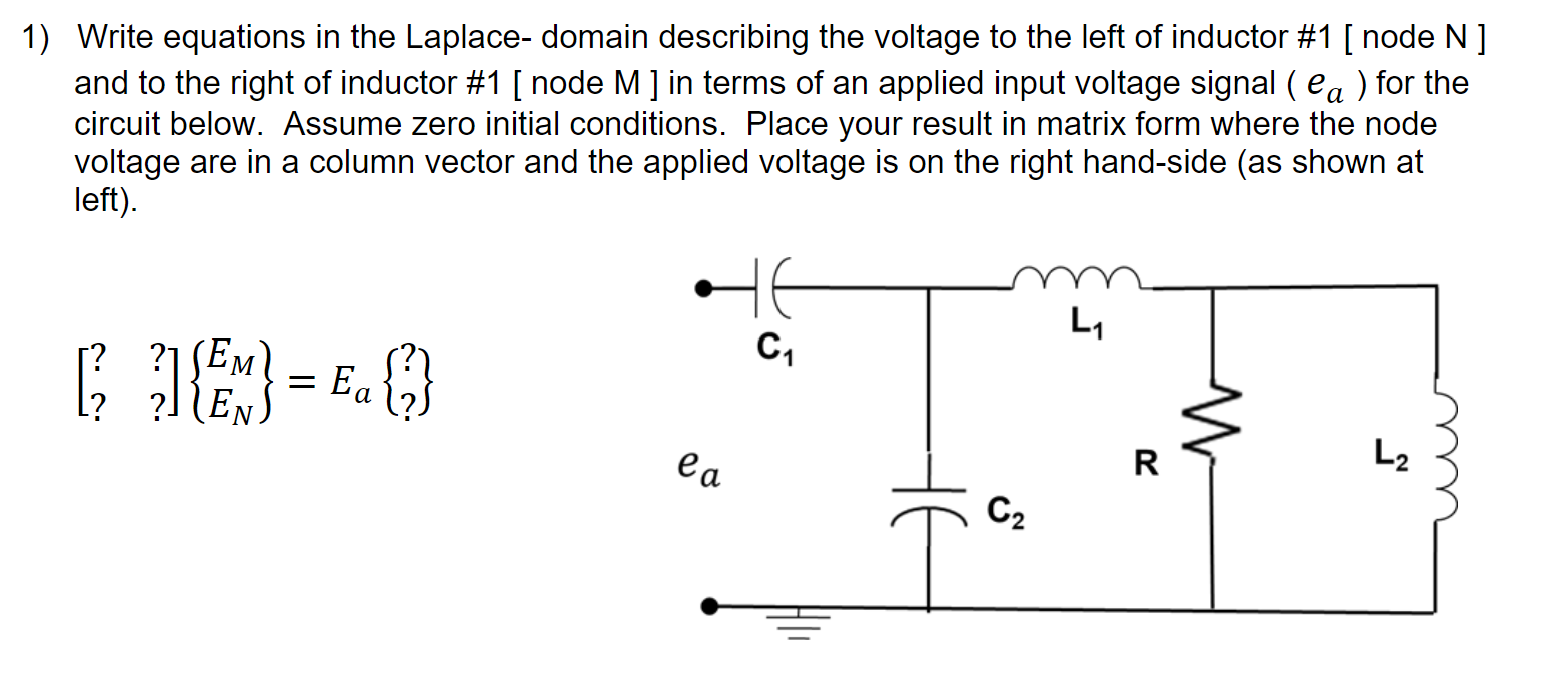
1) Write equations in the Laplace- domain describing the voltage to the left of inductor #1 [ node N] and to the right of

1) Write equations in the Laplace- domain describing the voltage to the left of inductor #1 [ node N] and to the right of inductor #1 [ node M ] in terms of an applied input voltage signal ( ea ) for the circuit below. Assume zero initial conditions. Place your result in matrix form where the node voltage are in a column vector and the applied voltage is on the right hand-side (as shown at left). SE M Ea [ ] { EN} = E { } L 1 C2 ea R 20 W L2
Step by Step Solution
There are 3 Steps involved in it
Step: 1

Get Instant Access to Expert-Tailored Solutions
See step-by-step solutions with expert insights and AI powered tools for academic success
Step: 2

Step: 3

Ace Your Homework with AI
Get the answers you need in no time with our AI-driven, step-by-step assistance
Get Started


