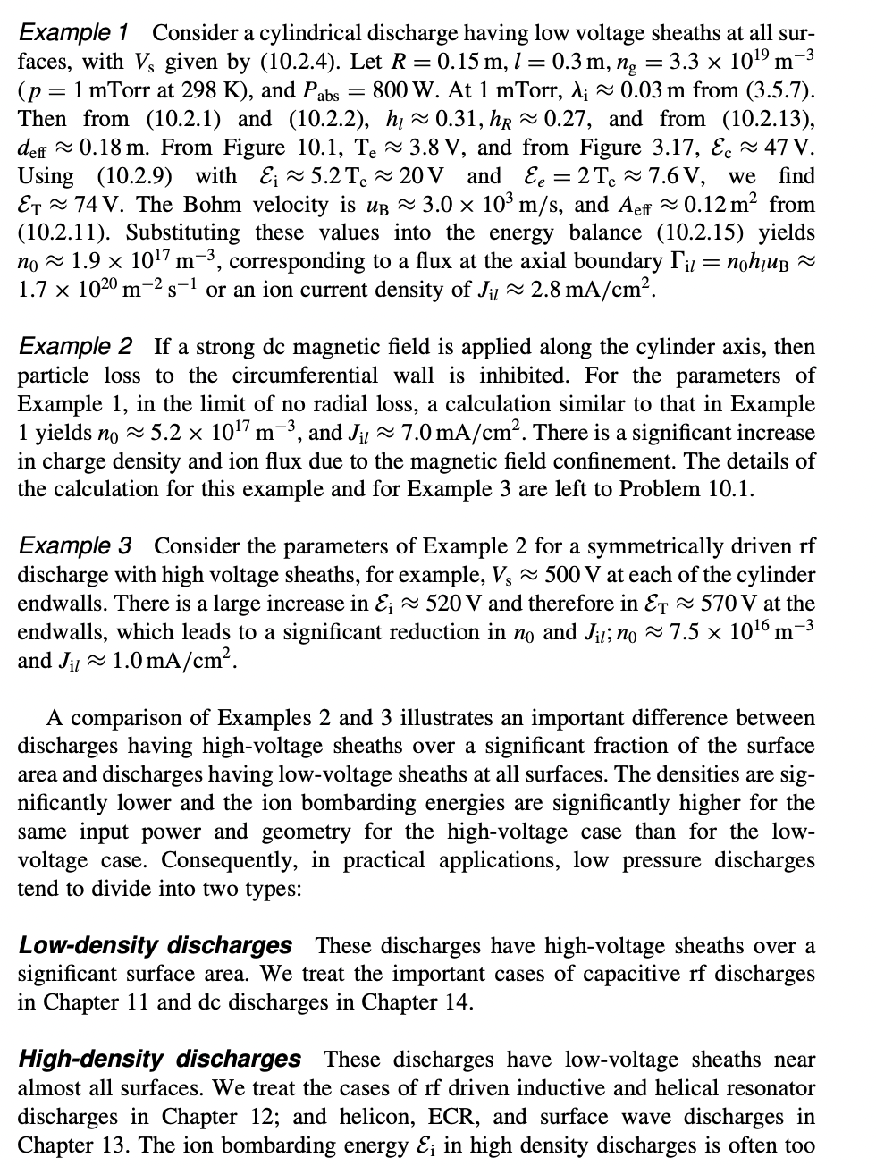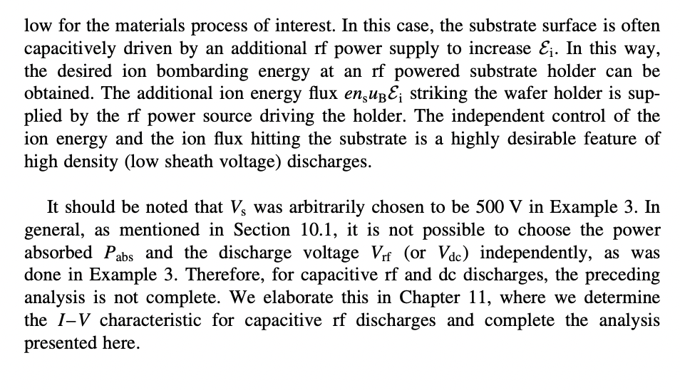


10.1. Low-Pressure Equilibrium (a) Using the method outlined in Example 1, calculate deff,Aeff,Te,Ec,Ei, ET, and uB, for Example 2. Confirm that n05.21017m3 and Jil7.0mA/cm2. (b) Repeat for Example 3 , confirming that n07.51016m3 and Jil1.0mA/cm2. Example 1 Consider a cylindrical discharge having low voltage sheaths at all surfaces, with Vs given by (10.2.4). Let R=0.15m,l=0.3m,ng=3.31019m3 ( p=1mTorr at 298K), and Pabs=800W. At 1mTorr,i0.03m from (3.5.7). Then from (10.2.1) and (10.2.2), hl0.31,hR0.27, and from (10.2.13), deff0.18m. From Figure 10.1,Te3.8V, and from Figure 3.17,Ec47V. Using (10.2.9) with Ei5.2Te20V and Ee=2Te7.6V, we find ET74V. The Bohm velocity is uB3.0103m/s, and Aeff0.12m2 from (10.2.11). Substituting these values into the energy balance (10.2.15) yields n01.91017m3, corresponding to a flux at the axial boundary il=n0hluB 1.71020m2s1 or an ion current density of Jil2.8mA/cm2. Example 2 If a strong dc magnetic field is applied along the cylinder axis, then particle loss to the circumferential wall is inhibited. For the parameters of Example 1, in the limit of no radial loss, a calculation similar to that in Example 1 yields n05.21017m3, and Jil7.0mA/cm2. There is a significant increase in charge density and ion flux due to the magnetic field confinement. The details of the calculation for this example and for Example 3 are left to Problem 10.1. Example 3 Consider the parameters of Example 2 for a symmetrically driven rf discharge with high voltage sheaths, for example, Vs500V at each of the cylinder endwalls. There is a large increase in Ei520V and therefore in ET570V at the endwalls, which leads to a significant reduction in n0 and Ji;n07.51016m3 and Jil1.0mA/cm2. A comparison of Examples 2 and 3 illustrates an important difference between discharges having high-voltage sheaths over a significant fraction of the surface area and discharges having low-voltage sheaths at all surfaces. The densities are significantly lower and the ion bombarding energies are significantly higher for the same input power and geometry for the high-voltage case than for the lowvoltage case. Consequently, in practical applications, low pressure discharges tend to divide into two types: Low-density discharges These discharges have high-voltage sheaths over a significant surface area. We treat the important cases of capacitive rf discharges in Chapter 11 and dc discharges in Chapter 14. High-density discharges These discharges have low-voltage sheaths near almost all surfaces. We treat the cases of rf driven inductive and helical resonator discharges in Chapter 12; and helicon, ECR, and surface wave discharges in Chapter 13. The ion bombarding energy Ei in high density discharges is often too low for the materials process of interest. In this case, the substrate surface is often capacitively driven by an additional rf power supply to increase Ei. In this way, the desired ion bombarding energy at an rf powered substrate holder can be obtained. The additional ion energy flux ensuBEi striking the wafer holder is supplied by the rf power source driving the holder. The independent control of the ion energy and the ion flux hitting the substrate is a highly desirable feature of high density (low sheath voltage) discharges. It should be noted that Vs was arbitrarily chosen to be 500V in Example 3. In general, as mentioned in Section 10.1, it is not possible to choose the power absorbed Pabs and the discharge voltage Vrf (or Vdc ) independently, as was done in Example 3. Therefore, for capacitive rf and dc discharges, the preceding analysis is not complete. We elaborate this in Chapter 11, where we determine the IV characteristic for capacitive rf discharges and complete the analysis presented here. 10.1. Low-Pressure Equilibrium (a) Using the method outlined in Example 1, calculate deff,Aeff,Te,Ec,Ei, ET, and uB, for Example 2. Confirm that n05.21017m3 and Jil7.0mA/cm2. (b) Repeat for Example 3 , confirming that n07.51016m3 and Jil1.0mA/cm2. Example 1 Consider a cylindrical discharge having low voltage sheaths at all surfaces, with Vs given by (10.2.4). Let R=0.15m,l=0.3m,ng=3.31019m3 ( p=1mTorr at 298K), and Pabs=800W. At 1mTorr,i0.03m from (3.5.7). Then from (10.2.1) and (10.2.2), hl0.31,hR0.27, and from (10.2.13), deff0.18m. From Figure 10.1,Te3.8V, and from Figure 3.17,Ec47V. Using (10.2.9) with Ei5.2Te20V and Ee=2Te7.6V, we find ET74V. The Bohm velocity is uB3.0103m/s, and Aeff0.12m2 from (10.2.11). Substituting these values into the energy balance (10.2.15) yields n01.91017m3, corresponding to a flux at the axial boundary il=n0hluB 1.71020m2s1 or an ion current density of Jil2.8mA/cm2. Example 2 If a strong dc magnetic field is applied along the cylinder axis, then particle loss to the circumferential wall is inhibited. For the parameters of Example 1, in the limit of no radial loss, a calculation similar to that in Example 1 yields n05.21017m3, and Jil7.0mA/cm2. There is a significant increase in charge density and ion flux due to the magnetic field confinement. The details of the calculation for this example and for Example 3 are left to Problem 10.1. Example 3 Consider the parameters of Example 2 for a symmetrically driven rf discharge with high voltage sheaths, for example, Vs500V at each of the cylinder endwalls. There is a large increase in Ei520V and therefore in ET570V at the endwalls, which leads to a significant reduction in n0 and Ji;n07.51016m3 and Jil1.0mA/cm2. A comparison of Examples 2 and 3 illustrates an important difference between discharges having high-voltage sheaths over a significant fraction of the surface area and discharges having low-voltage sheaths at all surfaces. The densities are significantly lower and the ion bombarding energies are significantly higher for the same input power and geometry for the high-voltage case than for the lowvoltage case. Consequently, in practical applications, low pressure discharges tend to divide into two types: Low-density discharges These discharges have high-voltage sheaths over a significant surface area. We treat the important cases of capacitive rf discharges in Chapter 11 and dc discharges in Chapter 14. High-density discharges These discharges have low-voltage sheaths near almost all surfaces. We treat the cases of rf driven inductive and helical resonator discharges in Chapter 12; and helicon, ECR, and surface wave discharges in Chapter 13. The ion bombarding energy Ei in high density discharges is often too low for the materials process of interest. In this case, the substrate surface is often capacitively driven by an additional rf power supply to increase Ei. In this way, the desired ion bombarding energy at an rf powered substrate holder can be obtained. The additional ion energy flux ensuBEi striking the wafer holder is supplied by the rf power source driving the holder. The independent control of the ion energy and the ion flux hitting the substrate is a highly desirable feature of high density (low sheath voltage) discharges. It should be noted that Vs was arbitrarily chosen to be 500V in Example 3. In general, as mentioned in Section 10.1, it is not possible to choose the power absorbed Pabs and the discharge voltage Vrf (or Vdc ) independently, as was done in Example 3. Therefore, for capacitive rf and dc discharges, the preceding analysis is not complete. We elaborate this in Chapter 11, where we determine the IV characteristic for capacitive rf discharges and complete the analysis presented here


