Answered step by step
Verified Expert Solution
Question
1 Approved Answer
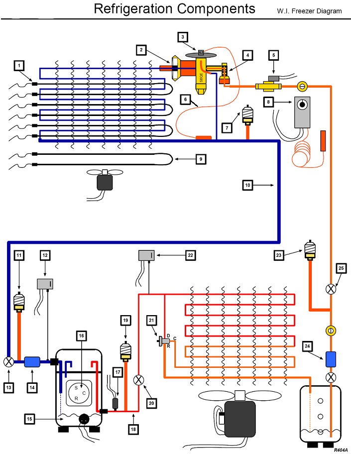
11 12 Refrigeration Components W.I. Freezer Diagram 14 15 16 2 19 17 18 20 22 v v 10 5 v < 23 v


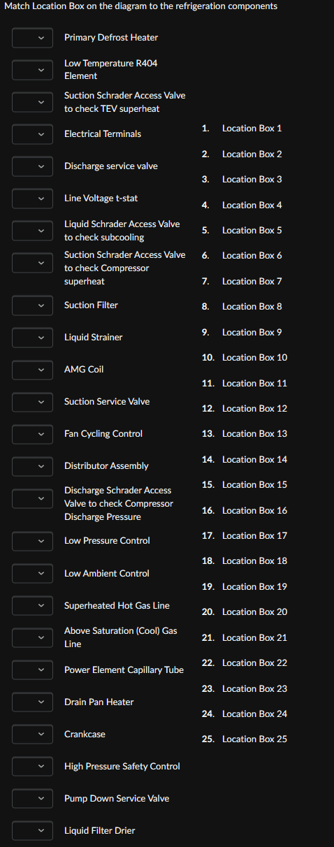
11 12 Refrigeration Components W.I. Freezer Diagram 14 15 16 2 19 17 18 20 22 v v 10 5 v < 23 v 24 25 R404A Match Location Box on the diagram to the refrigeration components Primary Defrost Heater Low Temperature R404 Element Suction Schrader Access Valve to check TEV superheat 1. Location Box 1 Electrical Terminals 2. Location Box 2 Discharge service valve 3. Location Box 3 Line Voltage t-stat 4. Location Box 4 Liquid Schrader Access Valve to check subcooling 5. Location Box 5 Suction Schrader Access Valve 6. Location Box 6 to check Compressor superheat 7. Location Box 7 Suction Filter 8. Location Box 8 9. Location Box 9 Liquid Strainer 10. Location Box 10 AMG Coil 11. Location Box 11 Suction Service Valve 12. Location Box 12 Fan Cycling Control 13. Location Box 13 14. Location Box 14 Distributor Assembly 15. Location Box 15 Discharge Schrader Access Valve to check Compressor 16. Location Box 16 Discharge Pressure 17. Location Box 17 Low Pressure Control 18. Location Box 18 Low Ambient Control 19. Location Box 19 Superheated Hot Gas Line 20. Location Box 20 Above Saturation (Cool) Gas 21. Location Box 21 Line 22. Location Box 22 Power Element Capillary Tube 23. Location Box 23 Drain Pan Heater 24. Location Box 24 Crankcase 25. Location Box 25 High Pressure Safety Control Pump Down Service Valve Liquid Filter Drier
Step by Step Solution
There are 3 Steps involved in it
Step: 1

Get Instant Access to Expert-Tailored Solutions
See step-by-step solutions with expert insights and AI powered tools for academic success
Step: 2

Step: 3

Ace Your Homework with AI
Get the answers you need in no time with our AI-driven, step-by-step assistance
Get Started


