Answered step by step
Verified Expert Solution
Question
1 Approved Answer
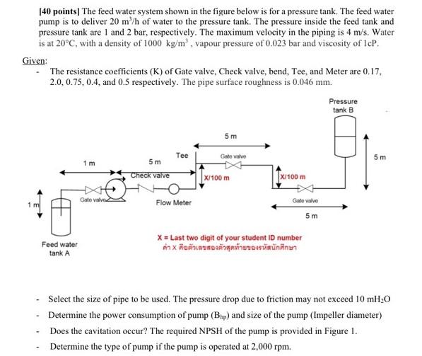
140 points| The feed water system shown in the figure below is for a pressure tank. The feed water pump is to deliver 20 m/h

140 points| The feed water system shown in the figure below is for a pressure tank. The feed water pump is to deliver 20 m/h of water to the pressure tank. The pressure inside the feed tank and pressure tank are 1 and 2 bar, respectively. The maximum velocity in the piping is 4 m/s. Water is at 20C, with a density of 1000 kg/m vapour pressure of 0.023 bar and viscosity of IcP. Given: The resistance coefficients (K) of Gate valve. Check valve, bend, Tee, and Meter are 0.17. 2.0.0.75, 0.4, and 0.5 respectively. The pipe surface roughness is 0.046 mm. Pressure tank B 5 m Tee Gate valve 5 m 1 m 5 m Check valve X100 m X/100 m Gate Valve Gate Valve 1 m Flow Meter 5 m Feed water tank A X = Last two digit of your student ID number X Select the size of pipe to be used. The pressure drop due to friction may not exceed 10 mH20 Determine the power consumption of pump (Bhp) and size of the pump (Impeller diameter) Does the cavitation occur? The required NPSH of the pump is provided in Figure 1. Determine the type of pump if the pump is operated at 2,000 rpm
Step by Step Solution
There are 3 Steps involved in it
Step: 1

Get Instant Access to Expert-Tailored Solutions
See step-by-step solutions with expert insights and AI powered tools for academic success
Step: 2

Step: 3

Ace Your Homework with AI
Get the answers you need in no time with our AI-driven, step-by-step assistance
Get Started


