Question
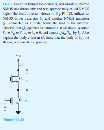
14.28 Anearlier form of logic circuits, now obsolete, utilized NMOS transistors only and was appropriately called NMOS logic. The basic inverter, shown in Fig. P14.28,
14.28 Anearlier form of logic circuits, now obsolete, utilized NMOS transistors only and was appropriately called NMOS logic. The basic inverter, shown in Fig. P14.28, utilizes an NMOS driver transistor Q1 and another NMOS transistor Q2, connected as a diode, forms the load of the inverter. Observe that Q2 operates in saturation at all times. Assume Vt1 = Vt2 = Vt , 1 = 2 = 0, and denote
kn1/kn2 by kr . Also neglect the body effect in Q2 (note that the body of Q2, not shown, is connected to ground).
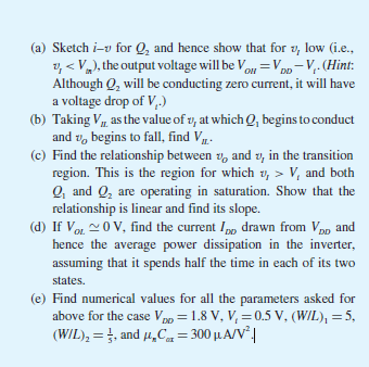
(a) Sketch iv for Q2 and hence show that for vI low (i.e., vI


14.28 An earlier formoflogiccircuits, now obsolete, utilized NMOS transistors only and was appropriately called NMOS logic. The basic inverter, shown in Fig. Pl4.28, utilizes an NMOS driver transistor Q and another NMOS 0,, connected as a diode, forms the load of the inverter. Observe that 0, operates in saturation at all times. Assume Az 30, and denote by k Also neglect the body effect in Q2 (note that the body of Q2, not shown, is connected to ground) Figure P14.28 14.28 An earlier formoflogiccircuits, now obsolete, utilized NMOS transistors only and was appropriately called NMOS logic. The basic inverter, shown in Fig. Pl4.28, utilizes an NMOS driver transistor Q and another NMOS 0,, connected as a diode, forms the load of the inverter. Observe that 0, operates in saturation at all times. Assume Az 30, and denote by k Also neglect the body effect in Q2 (note that the body of Q2, not shown, is connected to ground) Figure P14.28
Step by Step Solution
There are 3 Steps involved in it
Step: 1

Get Instant Access to Expert-Tailored Solutions
See step-by-step solutions with expert insights and AI powered tools for academic success
Step: 2

Step: 3

Ace Your Homework with AI
Get the answers you need in no time with our AI-driven, step-by-step assistance
Get Started


