Question: /1630 GENERAL PHYSICS II- ONLINE LABORATORY Summer 2 Activity 3: Investigating Parallel Circuits 1. Rearrange the components of your circuit in the workspace so that
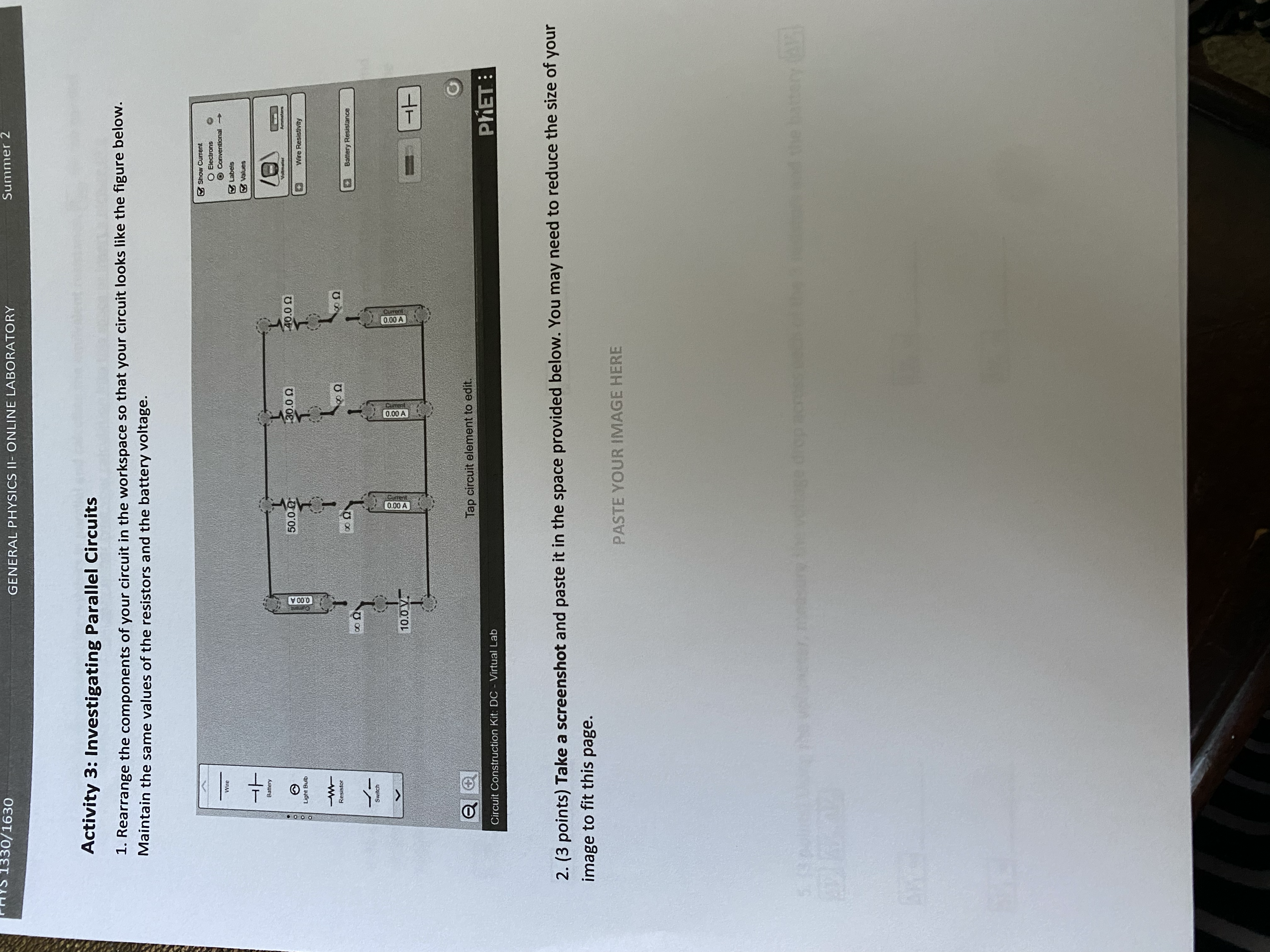
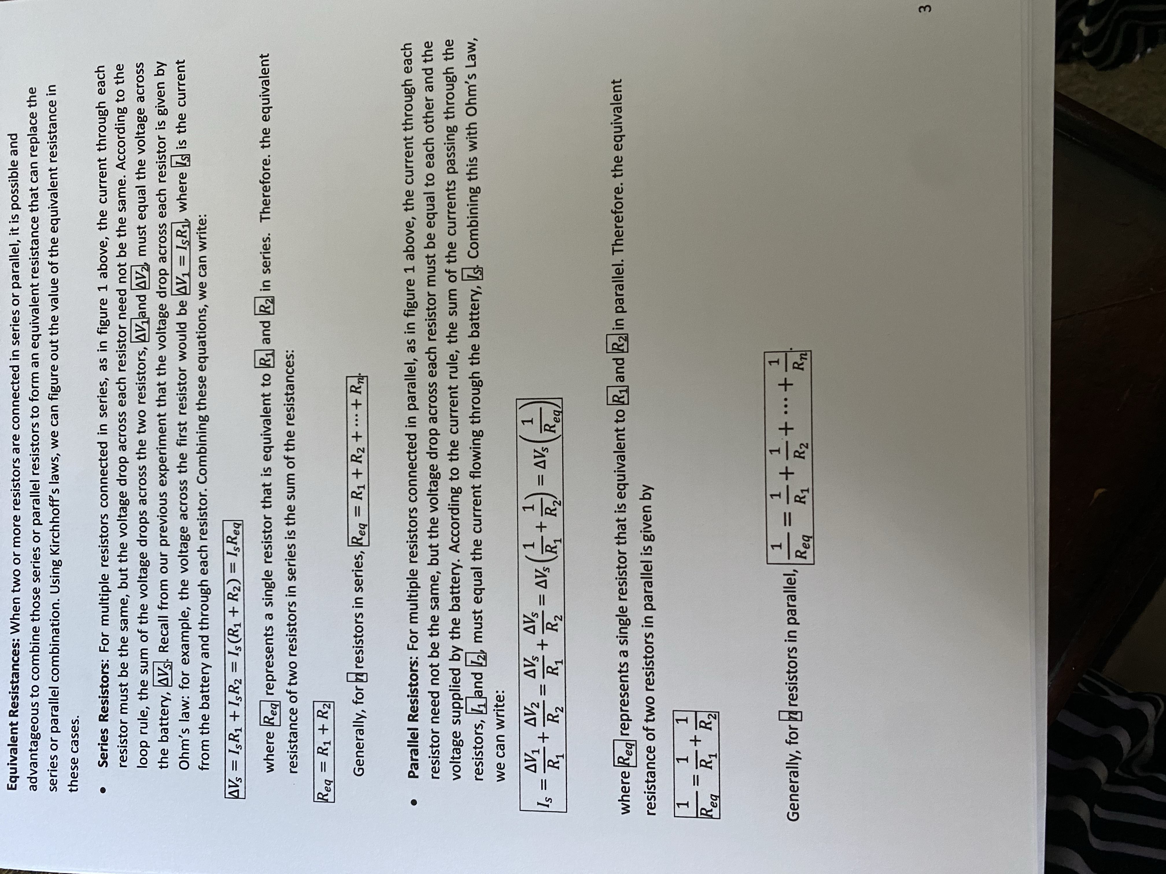
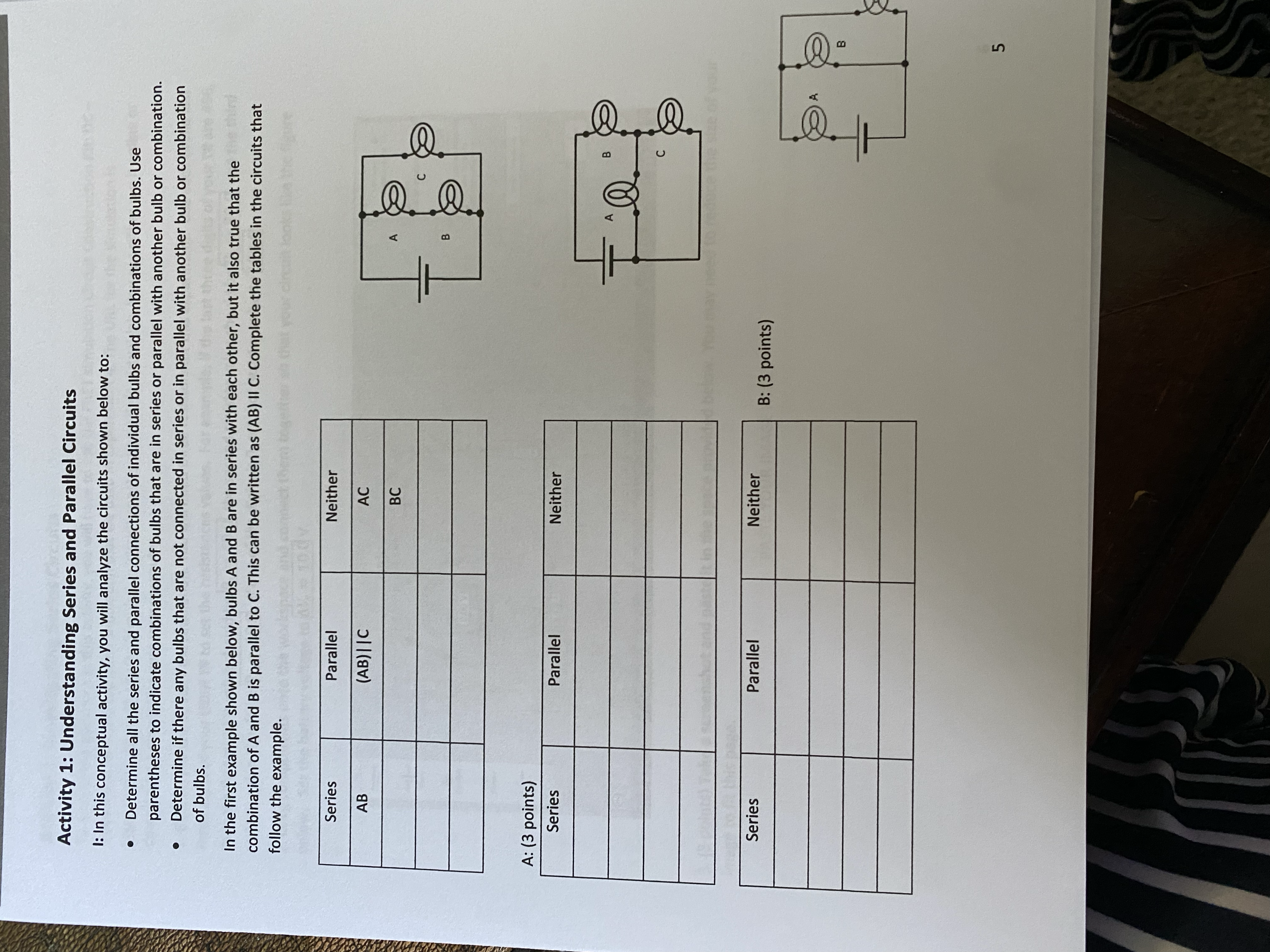
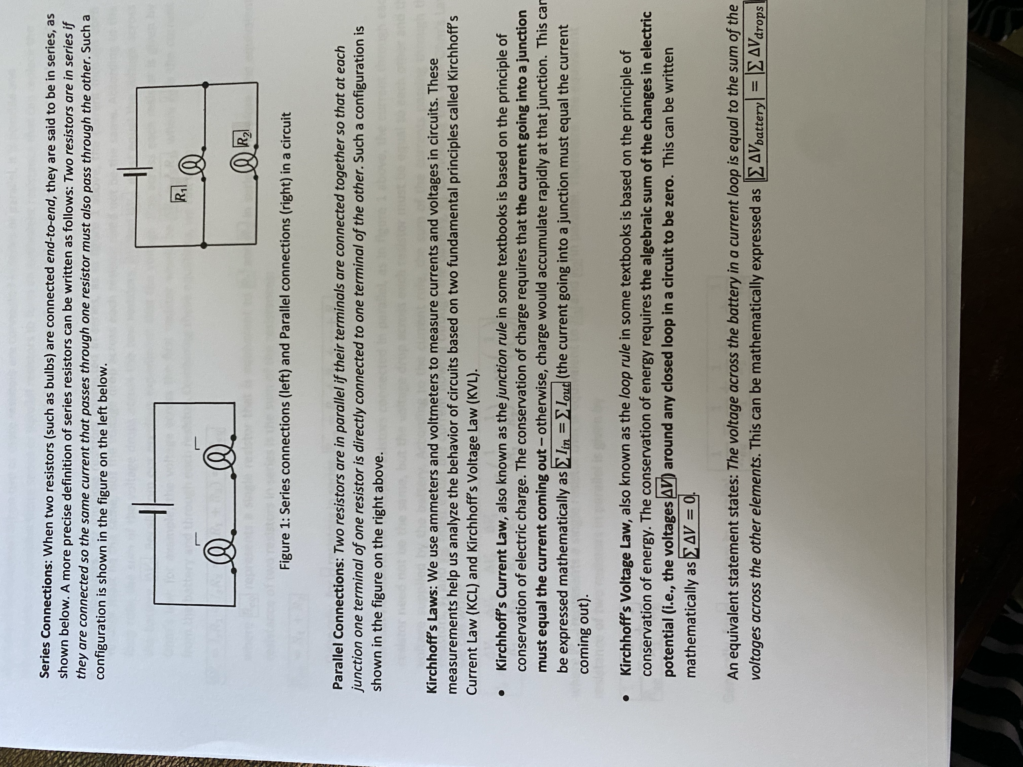
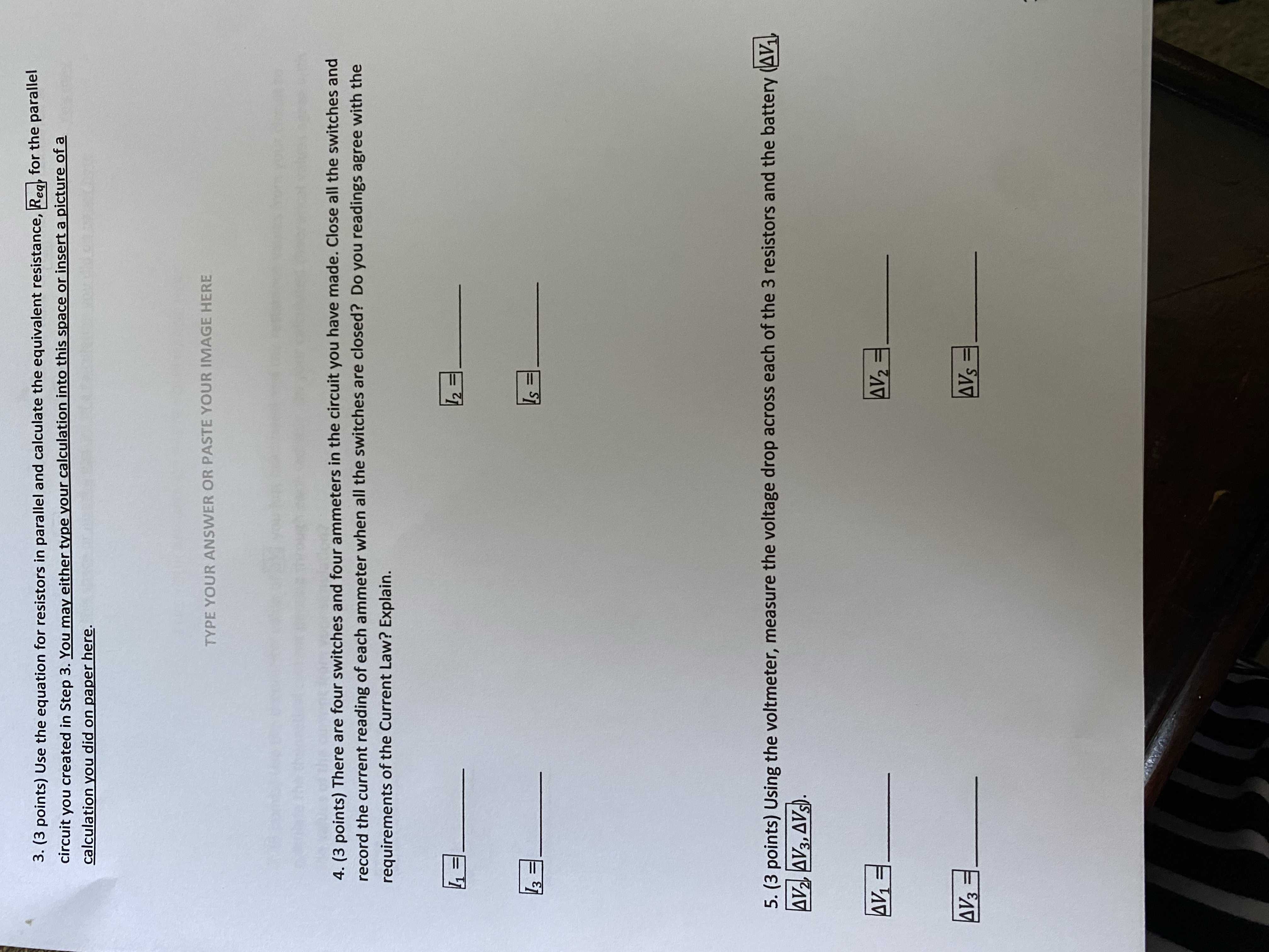
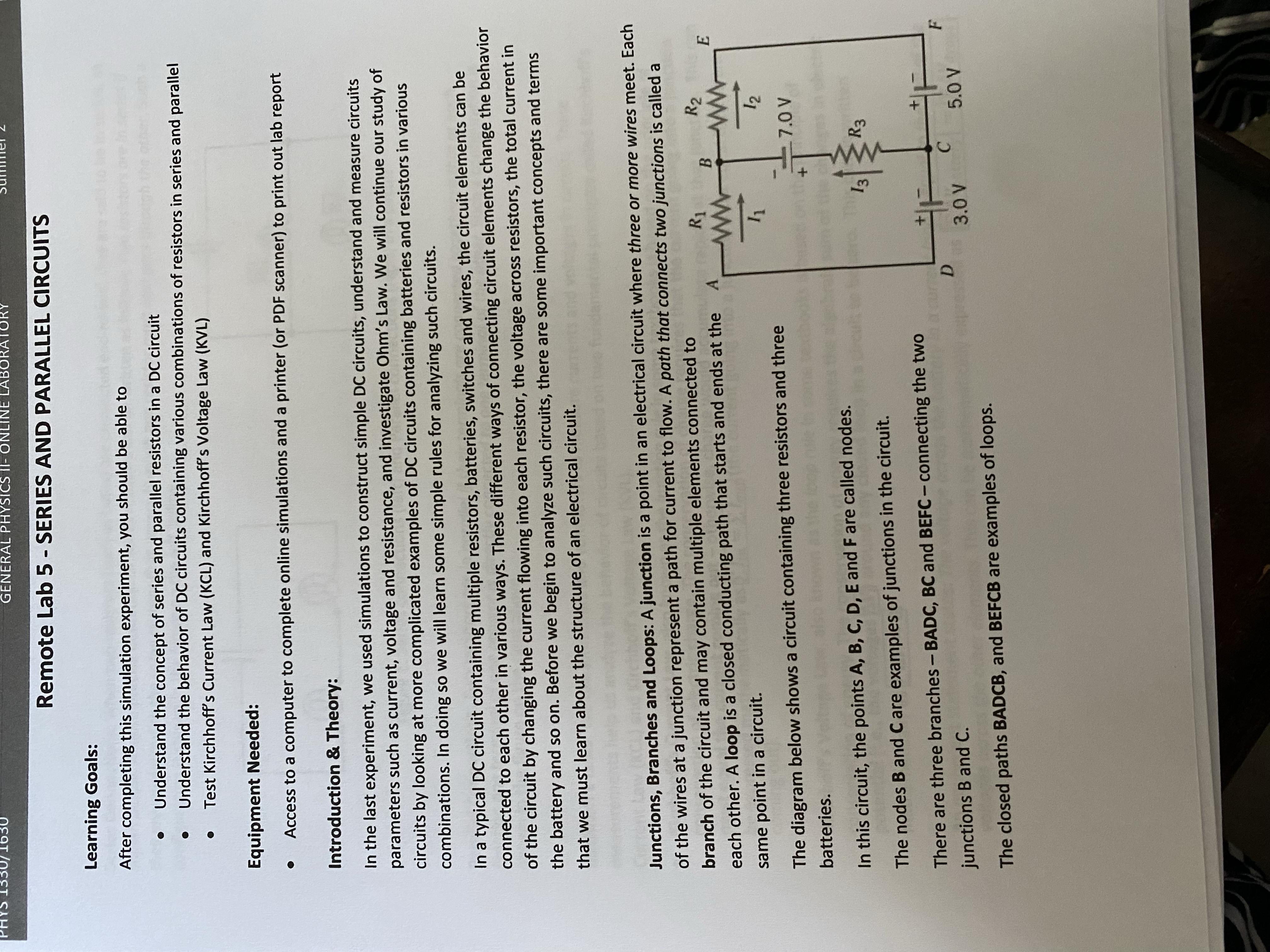
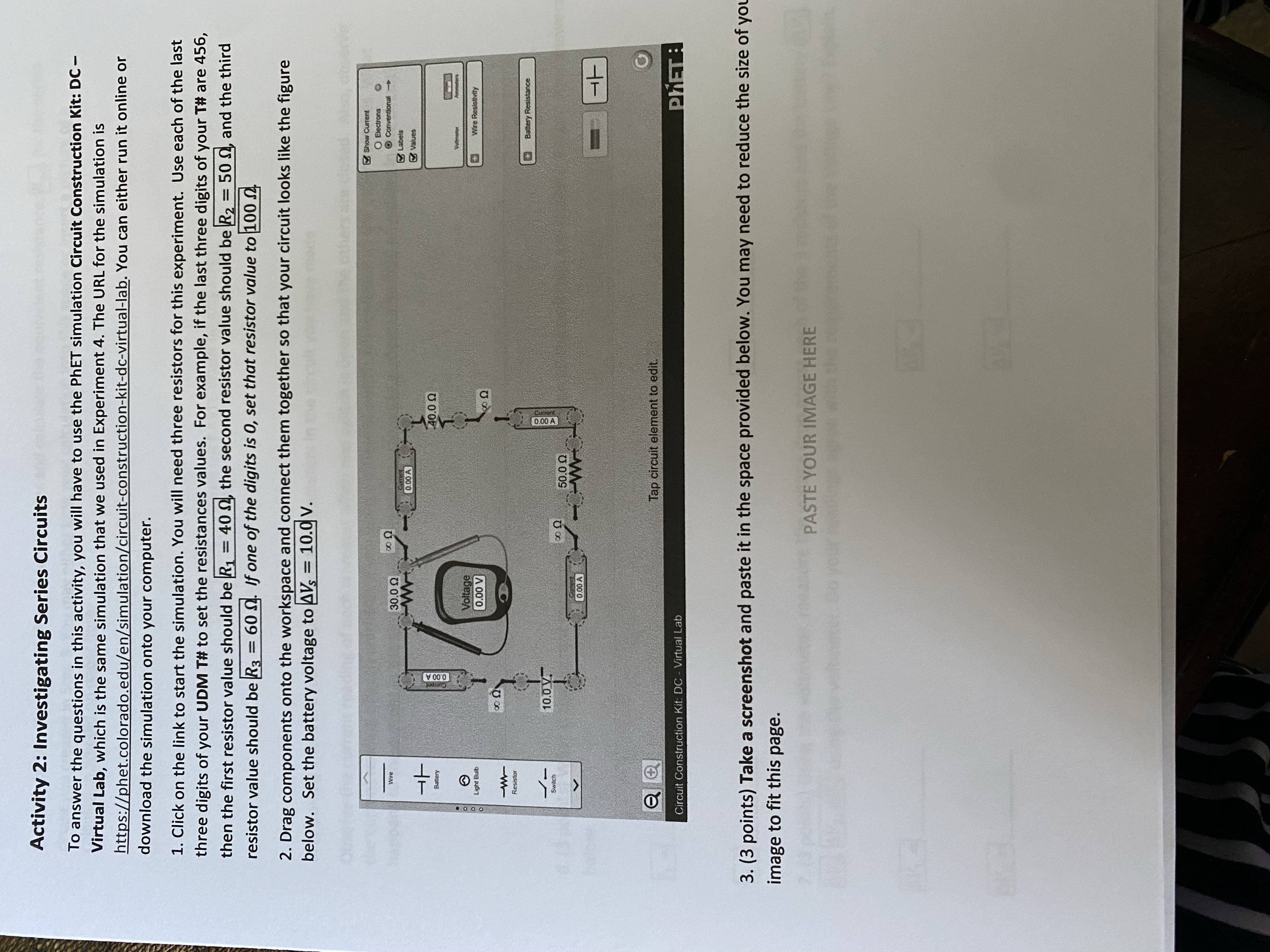
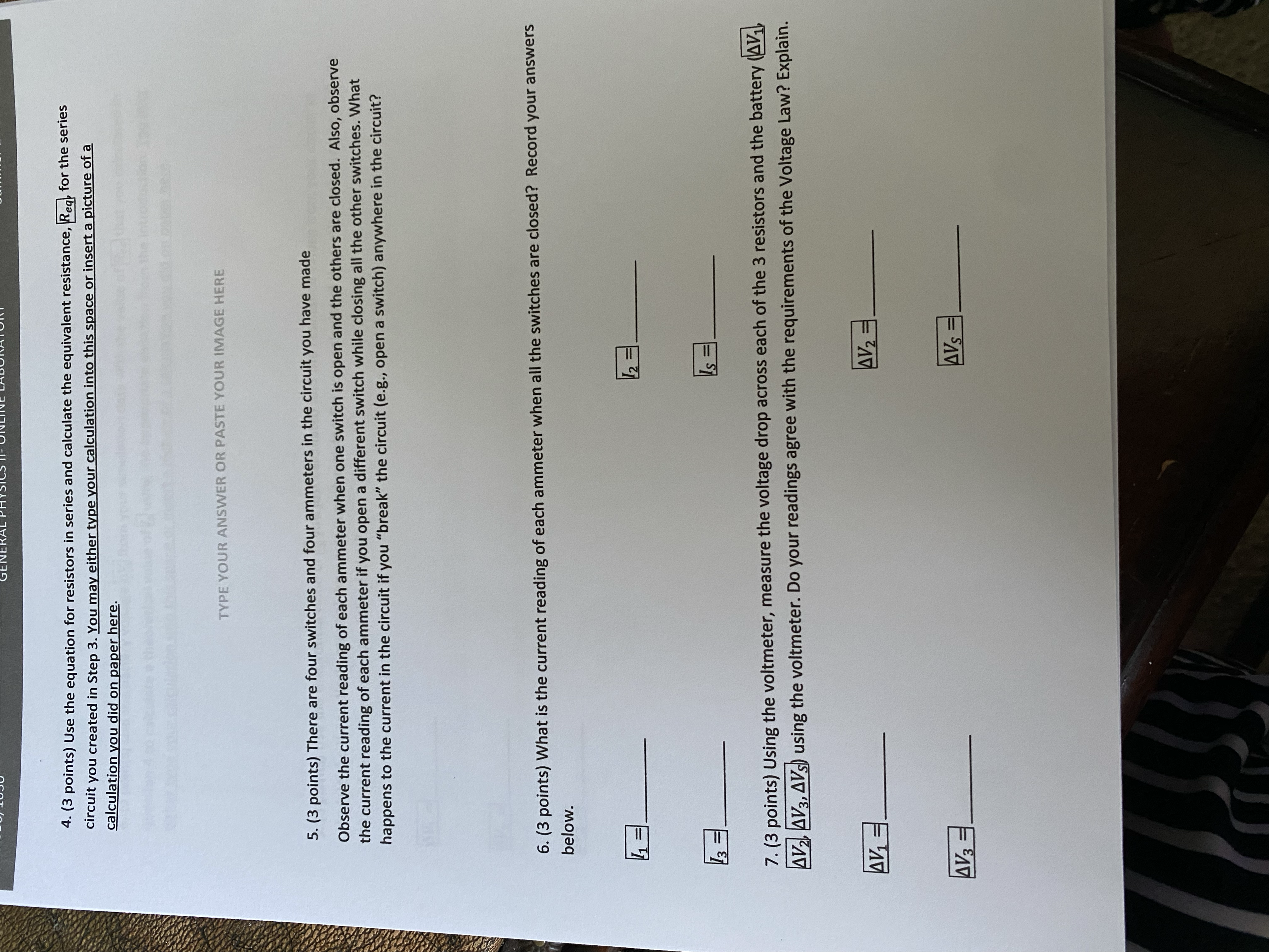
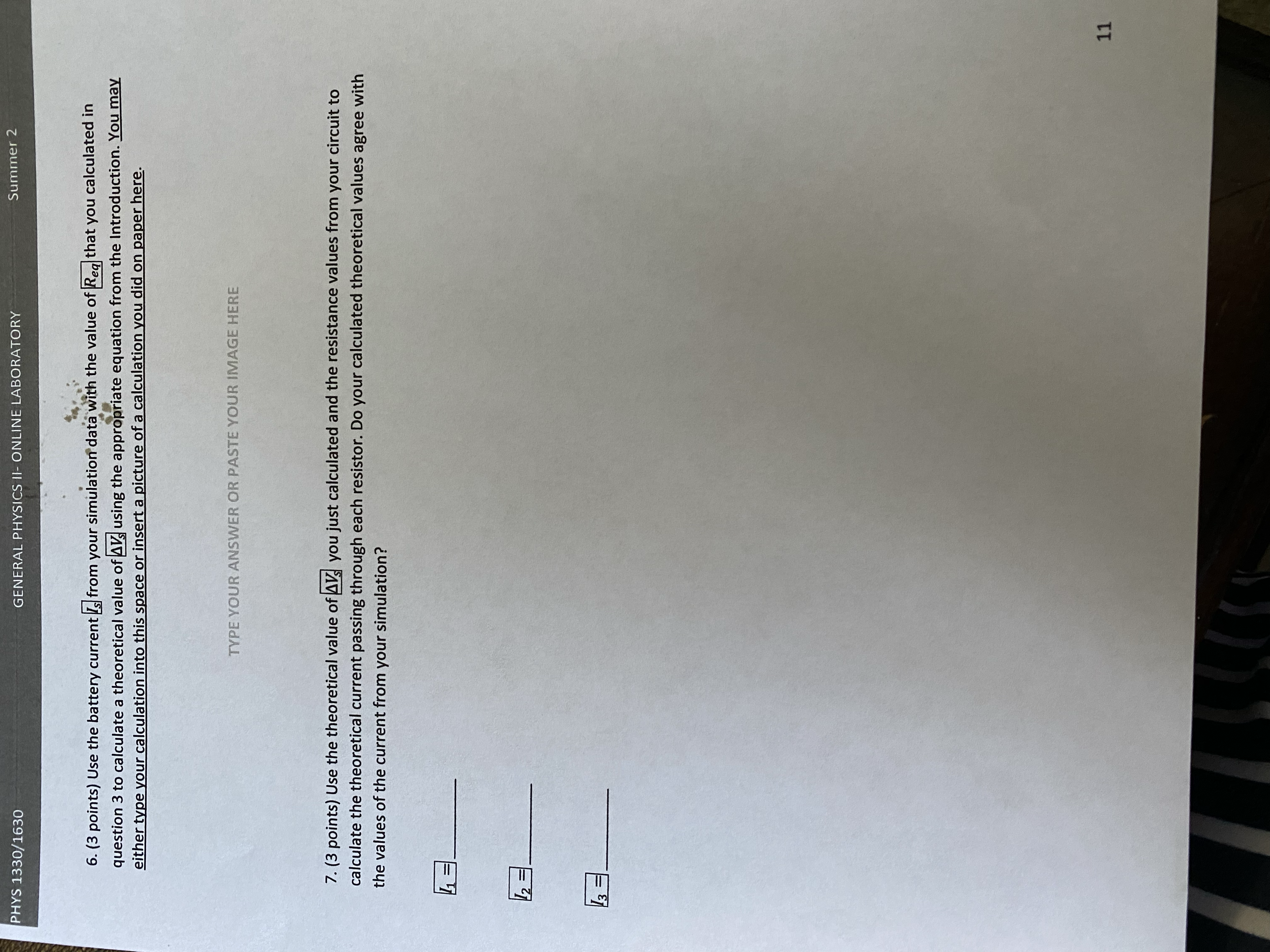
/1630 GENERAL PHYSICS II- ONLINE LABORATORY Summer 2 Activity 3: Investigating Parallel Circuits 1. Rearrange the components of your circuit in the workspace so that your circuit looks like the figure below. Maintain the same values of the resistors and the battery voltage. Show Current Electrons wire Conventional Labels Values 50.0 0 30.0 0 40.0 0 Wire Resistivity 10.00 A -M Resistor 60 0 Battery Resistance 0.00 A 0.00 A 0.00 A 10.0 V. Tap circuit element to edit. Circuit Construction Kit: DC - Virtual Lab PHET : 2. (3 points) Take a screenshot and paste it in the space provided below. You may need to reduce the size of your image to fit this page. PASTE YOUR IMAGE HEREEquivalent Resistances: When two or more resistors are connected in series or parallel, it is possible and advantageous to combine those series or parallel resistors to form an equivalent resistance that can replace the series or parallel combination. Using Kirchhoff's laws, we can figure out the value of the equivalent resistance in these cases. . Series Resistors: For multiple resistors connected in series, as in figure 1 above, the current through each resistor must be the same, but the voltage drop across each resistor need not be the same. According to the loop rule, the sum of the voltage drops across the two resistors, AV, and AV2, must equal the voltage across the battery, AVs. Recall from our previous experiment that the voltage drop across each resistor is given by Ohm's law: for example, the voltage across the first resistor would be AV, = IsR1, where Is is the current from the battery and through each resistor. Combining these equations, we can write AVs = IsR1 + IsR2 = Is(R1 + R2) = IsReq where Req represents a single resistor that is equivalent to R, and R2 in series. Therefore. the equivalent resistance of two resistors in series is the sum of the resistances: Req = R1 + R2 Generally, for n resistors in series, Req = R1 + R2 + ... + Rn . Parallel Resistors: For multiple resistors connected in parallel, as in figure 1 above, the current through each resistor need not be the same, but the voltage drop across each resistor must be equal to each other and the voltage supplied by the battery. According to the current rule, the sum of the currents passing through the resistors, 4 and 2, must equal the current flowing through the battery, Is- Combining this with Ohm's Law, we can write: AV1 , AV2 _ AVS + AVS - AVS (+ R7) = AVs( Reg) IS = RR2 R, RZ where Req represents a single resistor that is equivalent to R,| and R2 in parallel. Therefore. the equivalent resistance of two resistors in parallel is given by 1 Reg R, R2 Generally, for m resistors in parallel, 1 Reg R 1 R 2 It ... +1 RnActivity 1: Understanding Series and Parallel Circuits 1: In this conceptual activity, you will analyze the circuits shown below to: . Determine all the series and parallel connections of individual bulbs and combinations of bulbs. Use parentheses to indicate combinations of bulbs that are in series or parallel with another bulb or combination. Determine if there any bulbs that are not connected in series or in parallel with another bulb or combination of bulbs. In the first example shown below, bulbs A and B are in series with each other, but it also true that the combination of A and B is parallel to C. This can be written as (AB) II C. Complete the tables in the circuits that follow the example. Series Parallel Neither AB (AB)|IC U A: (3 points) Series Parallel Neither Series Parallel Neither B: (3 points)Series Connections: When two resistors (such as bulbs) are connected end-to-end, they are said to be in series, as shown below. A more precise definition of series resistors can be written as follows: Two resistors are in series if they are connected so the same current that passes through one resistor must also pass through the other. Such a configuration is shown in the figure on the left below. Figure 1: Series connections (left) and Parallel connections (right) in a circuit Parallel Connections: Two resistors are in parallel if their terminals are connected together so that at each junction one terminal of one resistor is directly connected to one terminal of the other. Such a configuration is shown in the figure on the right above. Kirchhoff's Laws: We use ammeters and voltmeters to measure currents and voltages in circuits. These measurements help us analyze the behavior of circuits based on two fundamental principles called Kirchhoff's Current Law (KCL) and Kirchhoff's Voltage Law (KVL). . Kirchhoff's Current Law, also known as the junction rule in some textbooks is based on the principle of conservation of electric charge. The conservation of charge requires that the current going into a junction must equal the current coming out - otherwise, charge would accumulate rapidly at that junction. This can be expressed mathematically as E lin = Elout (the current going into a junction must equal the current coming out). . Kirchhoff's Voltage Law, also known as the loop rule in some textbooks is based on the principle of conservation of energy. The conservation of energy requires the algebraic sum of the changes in electric potential (i.e., the voltages AV) around any closed loop in a circuit to be zero. This can be written mathematically as CAV = O An equivalent statement states: The voltage across the battery in a current loop is equal to the sum of the voltages across the other elements. This can be mathematically expressed as _ AVbattery| = [E AVdrops3. (3 points) Use the equation for resistors in parallel and calculate the equivalent resistance, Req for the parallel circuit you created in Step 3. You may either type your calculation into this space or insert a picture of a calculation you did on paper here TYPE YOUR ANSWER OR PASTE YOUR IMAGE HERE 4. (3 points) There are four switches and four ammeters in the circuit you have made. Close all the switches and record the current reading of each ammeter when all the switches are closed? Do you readings agree with the requirements of the Current Law? Explain. 12 = 13 = Is = 5. (3 points) Using the voltmeter, measure the voltage drop across each of the 3 resistors and the battery (AV1 AV2, AV3, AVs AV= AV2 = AV3= AVs =Remote Lab 5 - SERIES AND PARALLEL CIRCUITS Learning Goals: After completing this simulation experiment, you should be able to Understand the concept of series and parallel resistors in a DC circuit . . Understand the behavior of DC circuits containing various combinations of resistors in series and parallel . Test Kirchhoff's Current Law (KCL) and Kirchhoff's Voltage Law (KVL) Equipment Needed: . Access to a computer to complete online simulations and a printer (or PDF scanner) to print out lab report Introduction & Theory: In the last experiment, we used simulations to construct simple DC circuits, understand and measure circuits parameters such as current, voltage and resistance, and investigate Ohm's Law. We will continue our study of circuits by looking at more complicated examples of DC circuits containing batteries and resistors in various combinations. In doing so we will learn some simple rules for analyzing such circuits In a typical DC circuit containing multiple resistors, batteries, switches and wires, the circuit elements can be connected to each other in various ways. These different ways of connecting circuit elements change the behavior of the circuit by changing the current flowing into each resistor, the voltage across resistors, the total current in the battery and so on. Before we begin to analyze such circuits, there are some important concepts and terms that we must learn about the structure of an electrical circuit. Junctions, Branches and Loops: A junction is a point in an electrical circuit where three or more wires meet. Each of the wires at a junction represent a path for current to flow. A path that connects two junctions is called a branch of the circuit and may contain multiple elements connected to each other. A loop is a closed conducting path that starts and ends at the same point in a circuit. The diagram below shows a circuit containing three resistors and three batteries. In this circuit, the points A, B, C, D, E and F are called nodes. The nodes B and C are examples of junctions in the circuit. There are three branches - BADC, BC and BEFC - connecting the two + junctions B and C. D C 3.0 V 5.0 V The closed paths BADCB, and BEFCB are examples of loops.8. (3 points) Use the battery voltage AVs from your simulation data with the value of Req that you calculated in question 4 to calculate a theoretical value of Is using the appropriate equation from the Introduction. You may either type your calculation into this space or insert a picture of a calculation you did on paper here. TYPE YOUR ANSWER OR PASTE YOUR IMAGE HERE 9. (3 points) Use the theoretical value of Is you just calculated and the resistance values from your circuit to calculate the theoretical potential drop across each resistor. Do your calculated theoretical values agree with the values of the voltage from your simulation? AV= AV2= AV3=Activity 2: Investigating Series Circuits To answer the questions in this activity, you will have to use the PhET simulation Circuit Construction Kit: DC - Virtual Lab, which is the same simulation that we used in Experiment 4. The URL for the simulation is https://phet.colorado.edu/en/simulation/circuit-construction-kit-dc-virtual-lab. You can either run it online or download the simulation onto your computer 1. Click on the link to start the simulation. You will need three resistors for this experiment. Use each of the last three digits of your UDM T# to set the resistances values. For example, if the last three digits of your T# are 456, then the first resistor value should be R1 = 40 0, the second resistor value should be R2 = 50 , and the third resistor value should be R3 = 60 . If one of the digits is 0, set that resistor value to 100 n 2. Drag components onto the workspace and connect them together so that your circuit looks like the figure below. Set the battery voltage to AVs = 10.0 v Show Current Electrons 8 30.0 0 Conventional 0.00 A Labels Values -40.0 0 Voltage 0.00 V Wire Resistivity Resistor Battery Resistance 10.0 V. 0.00 A 50.0 0 0.00 A O Tap circuit element to edit. Circuit Construction Kit: DC - Virtual Lab PLET : 3. (3 points) Take a screenshot and paste it in the space provided below. You may need to reduce the size of you image to fit this page. PASTE YOUR IMAGE HERE4. (3 points) Use the equation for resistors in series and calculate the equivalent resistance, Req, for the series circuit you created in Step 3. You may either type your calculation into this space or insert a picture of a calculation you did on paper here TYPE YOUR ANSWER OR PASTE YOUR IMAGE HERE 5. (3 points) There are four switches and four ammeters in the circuit you have made Observe the current reading of each ammeter when one switch is open and the others are closed. Also, observe the current reading of each ammeter if you open a different switch while closing all the other switches. What happens to the current in the circuit if you "break" the circuit (e.g., open a switch) anywhere in the circuit? 6. (3 points) What is the current reading of each ammeter when all the switches are closed? Record your answers below. 3 = Is = 7. (3 points) Using the voltmeter, measure the voltage drop across each of the 3 resistors and the battery (AV, AV2 AV3, AVs) using the voltmeter. Do your readings agree with the requirements of the Voltage Law? Explain. AV= AV2 = AV3 = AVs =PHYS 1330/1630 GENERAL PHYSICS II- ONLINE LABORATORY Summer 2 6. (3 points) Use the battery current Is from your simulation data with the value of Req that you calculated in question 3 to calculate a theoretical value of AVs using the appropriate equation from the Introduction. You may either type your calculation into this space or insert a picture of a calculation you did on paper here. TYPE YOUR ANSWER OR PASTE YOUR IMAGE HERE 7. (3 points) Use the theoretical value of AVs you just calculated and the resistance values from your circuit to calculate the theoretical current passing through each resistor. Do your calculated theoretical values agree with the values of the current from your simulation
Step by Step Solution
There are 3 Steps involved in it

Get step-by-step solutions from verified subject matter experts


