

Question: 2 . 3 DATAPATH DESIGN To realize the 4 - bit Smart Climate Control system, the Datapath necessitates specific logical operations, comprising a 2 -
DATAPATH DESIGN
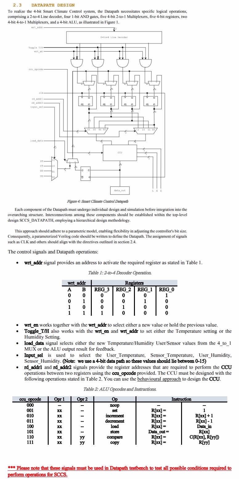
To realize the bit Smart Climate Control system, the Datapath necessitates specific logical operations, comprising a to Line decoder, four bit AND gates, five bit to Multiplexers, five bit registers, two bit to Multiplexers, and a bit ALU, as illustrated in Figure
Figure : Smart Climate Control Datapath
Each component of the Datapath must undergo individual design and simulation before integration into the overarching structure. Interconnections among these components should be established within the toplevel design SCCSDATAPATH, employing a hierarchical design methodology.
This approach should adhere to a parametric model, enabling flexibility in adjusting the controller's bit size. Consequently, a parameterized Verilog code should be written to define the Datapath. The assignment of signals such as CLK and others should align with the directives outlined in section
The control signals and Datapath operations:
wrtaddr signal provides an address to activate the required register as stated in Table
Table :to Decoder Operation.
tablewrt addr,RegistersABREGREGREGREG
wrten works together with the wrtaddr to select either a new value or hold the previous value.
ToggleTH also works with the witen and witaddr to set either the Temperature setting or the Humidity Setting.
loaddata signal selects either the new TemperatureHumidity UserSensor values from the to MUX or the ALU output result for feedback.
Inputsel is used to select the UserTemperature, SensorTemperature, UserHumidity, SensorHumidity. Note: we use a bit data path so these values should lie between
rdaddr and rdaddr signals provide the register addresses that are required to perform the CCU operations between two registers using the ccuopcode provided. The CCU must be designed with the following operations stated in Table You can use the behavioural approach to design the CCU.
Table : ALUOpcodes and Instructions.
tableccu opcode,Opr Opr OpInstructionnoop,times Rtimes times increment,Rtimes Rtimes times decrement,Rtimes Rtimes xxload,Rtimes Dataintimes store,Dataout Rbar times times yycompare,Rtimes CRtimes Ryytimes yycopy,Rtimes Ryy
Please note that these signals must be used in Datapath testbench to test all possible conditions required to p
Step by Step Solution
There are 3 Steps involved in it
1 Expert Approved Answer
Step: 1 Unlock

Question Has Been Solved by an Expert!
Get step-by-step solutions from verified subject matter experts
Step: 2 Unlock
Step: 3 Unlock