Answered step by step
Verified Expert Solution
Question
1 Approved Answer
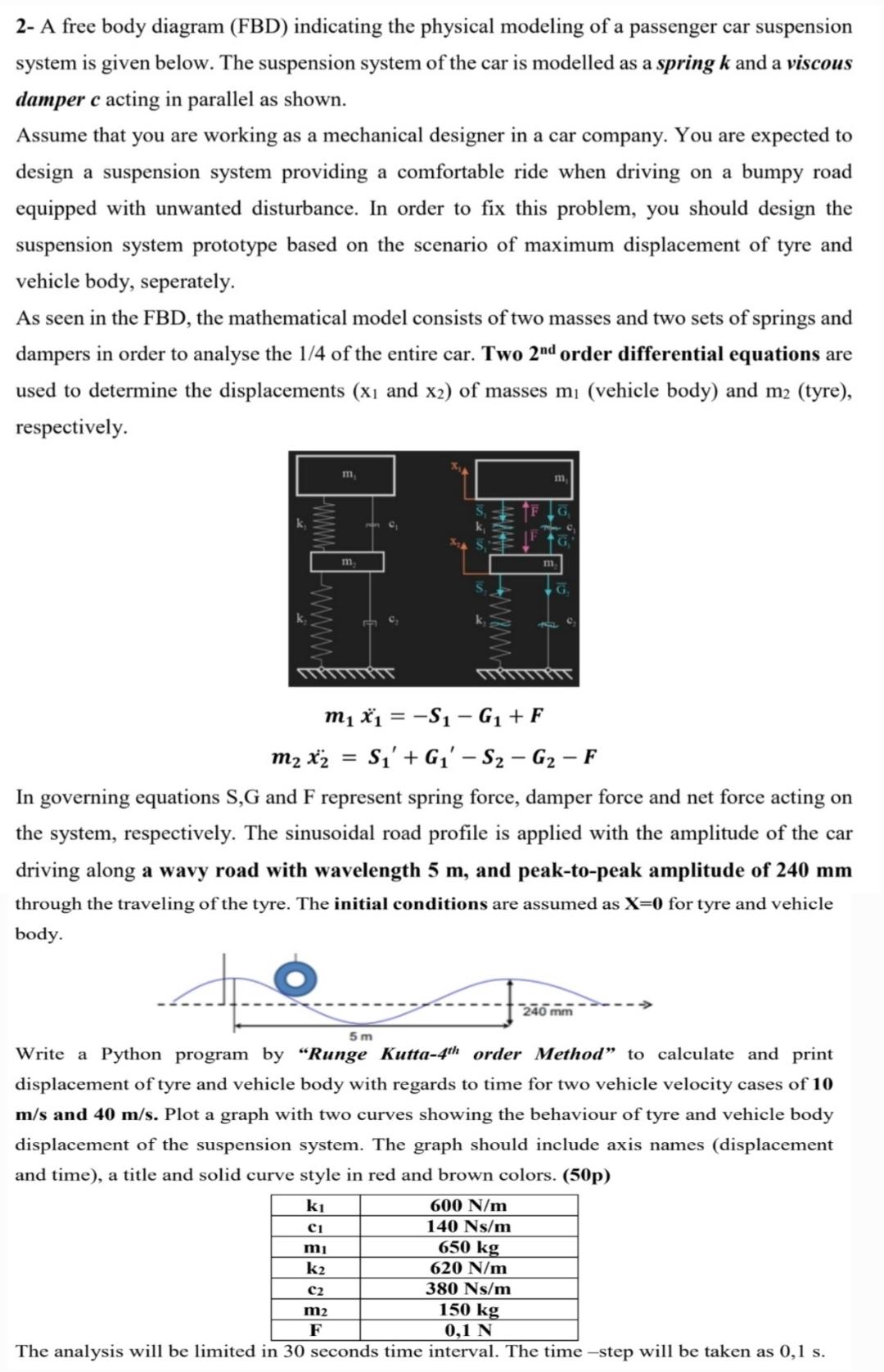
2- A free body diagram (FBD) indicating the physical modeling of a passenger car suspension system is given below. The suspension system of the

2- A free body diagram (FBD) indicating the physical modeling of a passenger car suspension system is given below. The suspension system of the car is modelled as a spring k and a viscous damper c acting in parallel as shown. Assume that you are working as a mechanical designer in a car company. You are expected to design a suspension system providing a comfortable ride when driving on a bumpy road equipped with unwanted disturbance. order to fix this problem, you should design the suspension system prototype based on the scenario of maximum displacement of tyre and vehicle body, seperately. As seen in the FBD, the mathematical model consists of two masses and two sets of springs and dampers in order to analyse the 1/4 of the entire car. Two 2nd order differential equations are used to determine the displacements (x and x2) of masses m (vehicle body) and m (tyre), respectively. k 1552 m, C1 m mi k C2 m2 F PTT 5m www m x = -S- G + F m x = S' + G-S - G - F In governing equations S,G and F represent spring force, damper force and net force acting on the system, respectively. The sinusoidal road profile is applied with the amplitude of the car driving along a wavy road with wavelength 5 m, and peak-to-peak amplitude of 240 mm through the traveling of the tyre. The initial conditions are assumed as X=0 for tyre and vehicle body. m m G. Write a Python program by "Runge Kutta-4th order Method" to calculate and print displacement of tyre and vehicle body with regards to time for two vehicle velocity cases of 10 m/s and 40 m/s. Plot a graph with two curves showing the behaviour of tyre and vehicle body displacement of the suspension system. The graph should include axis names (displacement and time), a title and solid curve style in red and brown colors. (50p) C 600 N/m 140 Ns/m 650 kg 620 N/m 380 Ns/m 150 kg 0,1 N The analysis will be limited in 30 seconds time interval. The time-step will be taken as 0,1 s. PTT 240 mm
Step by Step Solution
There are 3 Steps involved in it
Step: 1
The question requires us to implement a numerical solution for a system of secondorder differential equations using the RungeKutta 4th order method Specifically well be analyzing a quartercar model wh...
Get Instant Access to Expert-Tailored Solutions
See step-by-step solutions with expert insights and AI powered tools for academic success
Step: 2

Step: 3

Ace Your Homework with AI
Get the answers you need in no time with our AI-driven, step-by-step assistance
Get Started


