Answered step by step
Verified Expert Solution
Question
1 Approved Answer
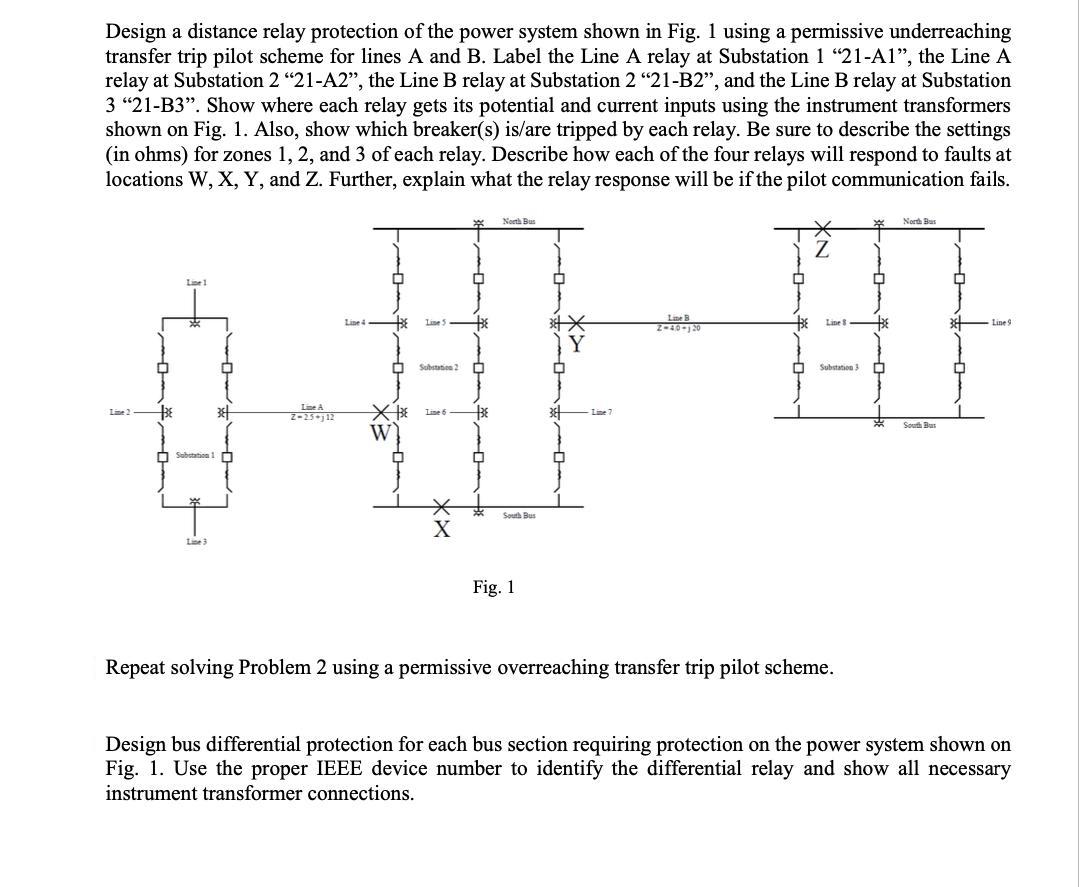
Design a distance relay protection of the power system shown in Fig. 1 using a permissive underreaching transfer trip pilot scheme for lines A

Design a distance relay protection of the power system shown in Fig. 1 using a permissive underreaching transfer trip pilot scheme for lines A and B. Label the Line A relay at Substation 1 "21-A1", the Line A relay at Substation 2 "21-A2", the Line B relay at Substation 2 "21-B2", and the Line B relay at Substation 3 "21-B3". Show where each relay gets its potential and current inputs using the instrument transformers shown on Fig. 1. Also, show which breaker(s) is/are tripped by each relay. Be sure to describe the settings (in ohms) for zones 1, 2, and 3 of each relay. Describe how each of the four relays will respond to faults at locations W, X, Y, and Z. Further, explain what the relay response will be if the pilot communication fails. Line 2 BE Line 1 * Substation 1 Line 3 38 Line A Z-25-112 Line 4 X3E W Q Line 5 Substation 2 Line 6 BE North Bus South Bus Fig. 1 Line B 2-40-120 Line 8 Substation 3 Repeat solving Problem 2 using a permissive overreaching transfer trip pilot scheme. BE North Bus South Bus 38 Line 9 Design bus differential protection for each bus section requiring protection on the power system shown on Fig. 1. Use the proper IEEE device number to identify the differential relay and show all necessary instrument transformer connections.
Step by Step Solution
★★★★★
3.54 Rating (189 Votes )
There are 3 Steps involved in it
Step: 1
The permissive underreaching transfer trip PUTT pilot scheme is a type of distance relay protection that is used to protect transmission lines It oper...
Get Instant Access to Expert-Tailored Solutions
See step-by-step solutions with expert insights and AI powered tools for academic success
Step: 2

Step: 3

Ace Your Homework with AI
Get the answers you need in no time with our AI-driven, step-by-step assistance
Get Started


