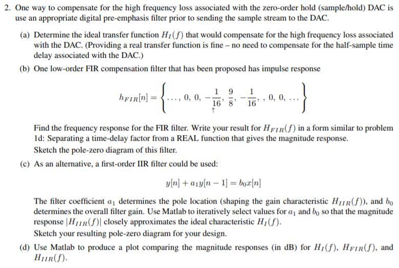
2. One way to compensate for the high frequency loss associated with the zero-order hold (sample/hold) DAC is use an appropriate digital pre-emphasis filter prior to sending the sample stream to the DAC. (a) Determine the ideal transfer function HI(f) that would compensate for the high frequency loss associated with the DAC. (Providing a real transfer function is fine- no need to compensate for the half-sample time delay associated with the DAC.) (b) One low-order FIR compensation filter that has been proposed has impulse response hFIRIn0, 0, 16 8' 16 Find the frequency response for the FIR filter. Write your result for HFIR(f) in a form similar to problem ld: Separating a time-delay factor from a REAL function that gives the magnitude response. Sketch the pole-zero diagram of this filter. (c) As an alternative, a first-order IIR filter could be used: The filter coefficient a determines the pole location (shaping the gain characteristic HIIR(f)), and bo determines the overall filter gain. Use Matlab to iteratively select values for a1 and bo so that the magnitude response |H1|R( closely approximates the ideal characteristic H1(f). Sketch your resulting pole-zero diagram for your design. (d) Use Matlab to produce a plot comparing the magnitude responses (in dB) for Hr(f), HFIR(f), and BR) 2. One way to compensate for the high frequency loss associated with the zero-order hold (sample/hold) DAC is use an appropriate digital pre-emphasis filter prior to sending the sample stream to the DAC. (a) Determine the ideal transfer function HI(f) that would compensate for the high frequency loss associated with the DAC. (Providing a real transfer function is fine- no need to compensate for the half-sample time delay associated with the DAC.) (b) One low-order FIR compensation filter that has been proposed has impulse response hFIRIn0, 0, 16 8' 16 Find the frequency response for the FIR filter. Write your result for HFIR(f) in a form similar to problem ld: Separating a time-delay factor from a REAL function that gives the magnitude response. Sketch the pole-zero diagram of this filter. (c) As an alternative, a first-order IIR filter could be used: The filter coefficient a determines the pole location (shaping the gain characteristic HIIR(f)), and bo determines the overall filter gain. Use Matlab to iteratively select values for a1 and bo so that the magnitude response |H1|R( closely approximates the ideal characteristic H1(f). Sketch your resulting pole-zero diagram for your design. (d) Use Matlab to produce a plot comparing the magnitude responses (in dB) for Hr(f), HFIR(f), and BR)


