Answered step by step
Verified Expert Solution
Question
1 Approved Answer
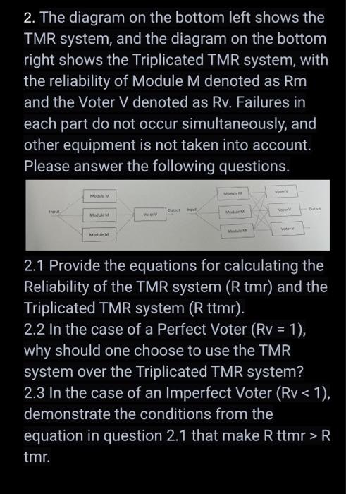
2. The diagram on the bottom left shows the TMR system, and the diagram on the bottom right shows the Triplicated TMR system, with

2. The diagram on the bottom left shows the TMR system, and the diagram on the bottom right shows the Triplicated TMR system, with the reliability of Module M denoted as Rm and the Voter V denoted as Rv. Failures in each part do not occur simultaneously, and other equipment is not taken into account. Please answer the following questions. M Medule M MM output h Module M 2.1 Provide the equations for calculating the Reliability of the TMR system (R tmr) and the Triplicated TMR system (R ttmr). 2.2 In the case of a Perfect Voter (Rv = 1), why should one choose to use the TMR system over the Triplicated TMR system? 2.3 In the case of an Imperfect Voter (Rv < 1), demonstrate the conditions from the equation in question 2.1 that make R ttmr > R tmr.
Step by Step Solution
There are 3 Steps involved in it
Step: 1

Get Instant Access to Expert-Tailored Solutions
See step-by-step solutions with expert insights and AI powered tools for academic success
Step: 2

Step: 3

Ace Your Homework with AI
Get the answers you need in no time with our AI-driven, step-by-step assistance
Get Started


