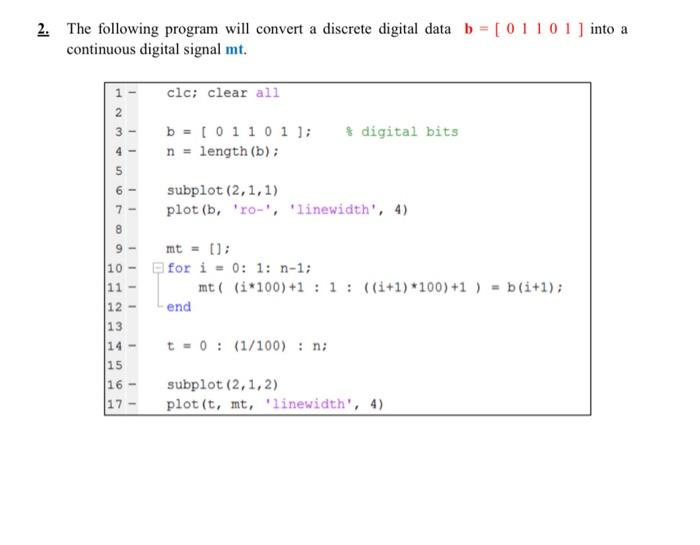
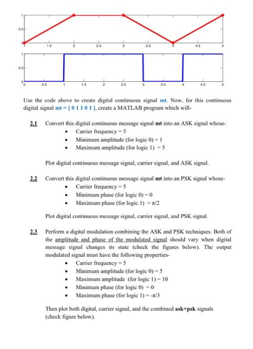
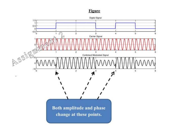
2. The following program will convert a discrete digital data b = [0110 1 ) into a continuous digital signal mt. - clc; clear all N 2 3 - 1 b = [01101]; n = length(b); $ digital bits - . Joon 11 subplot (2,1,1) plot (b, ro-', 'linewidth', 4) 10 -- mt = []; for i = 0: 1: n-1; mt ( (i*100) +1 : 1 : ((i+1)*100) +1 ) = b(i+1); 11 - 12 - end 13 t = 0 : (1/100) : n; 14 - 15 16 - 17 - subplot (2,1,2) plot(t, mt, 'linewidth', 4) 0:51 35 os 05 3.5 5 Use the code above to create digital continuous signal mt. Now, for this continuous digital signal mt-101101), create a MATLAB program which will 2.1 Convert this digital continuous message signal mt into an ASK signal whose- Carrier frequency - 5 Minimum amplitude (for logic 0) - 1 Maximum amplitude (for logic 1) - 5 Plot digital continuous message signal, carrier signal, and ASK signal. 2.2 Convert this digital continuous message signal mt into an PSK signal whose Carrier frequency=5 Minimum phase (for logic 0) = 0 Maximum phase (for logic 1) = 1/2 Plot digital continuous message signal, carrier signal, and PSK signal. 2.3 Perform a digital modulation combining the ASK and PSK techniques. Both of the amplitude and phase of the modulated signal should vary when digital message signal changes its state (check the figures below). The output modulated signal must have the following properties. Carrier frequency=5 Minimum amplitude (for logic 0) - 5 Maximum amplitude (for logic 1) = 10 Minimum phase (for logic 0) = 0 Maximum phase (for logic 1)=-1/3 Then plot both digital carrier signal, and the combined ask+psk signals (check figure below). Figure Digital Signal 1.5 1 0.5 0 -0.5 3 Carrier Signal Combined Modulated Signal Assign ihnen min wwwwwwwww 4 1 Both amplitude and phase change at these points