Question
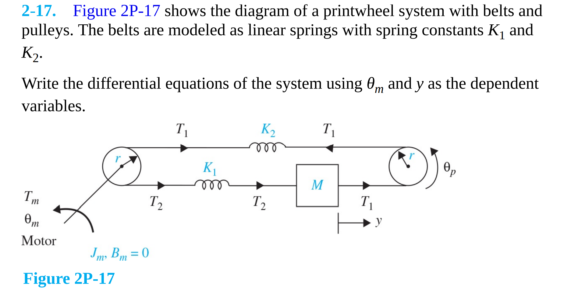
2-17. Figure 2P-17 shows the diagram of a printwheel system with belts and pulleys. The belts are modeled as linear springs with spring constants

2-17. Figure 2P-17 shows the diagram of a printwheel system with belts and pulleys. The belts are modeled as linear springs with spring constants K and K. Write the differential equations of the system using 0m and y as the dependent variables. Tm 0m Motor Jm, Bm = 0 Figure 2P-17 T T K m ooo K T T M T y Op
Step by Step Solution
There are 3 Steps involved in it
Step: 1

Get Instant Access to Expert-Tailored Solutions
See step-by-step solutions with expert insights and AI powered tools for academic success
Step: 2

Step: 3

Ace Your Homework with AI
Get the answers you need in no time with our AI-driven, step-by-step assistance
Get StartedRecommended Textbook for
Control Systems Engineering
Authors: Norman S. Nise
7th Edition
1118170512, 978-1118170519
Students also viewed these Mechanical Engineering questions
Question
Answered: 1 week ago
Question
Answered: 1 week ago
Question
Answered: 1 week ago
Question
Answered: 1 week ago
Question
Answered: 1 week ago
Question
Answered: 1 week ago
Question
Answered: 1 week ago
Question
Answered: 1 week ago
Question
Answered: 1 week ago
Question
Answered: 1 week ago
Question
Answered: 1 week ago
Question
Answered: 1 week ago
Question
Answered: 1 week ago
Question
Answered: 1 week ago
Question
Answered: 1 week ago
Question
Answered: 1 week ago
Question
Answered: 1 week ago
Question
Answered: 1 week ago
Question
Answered: 1 week ago
Question
Answered: 1 week ago
View Answer in SolutionInn App


