Answered step by step
Verified Expert Solution
Question
1 Approved Answer
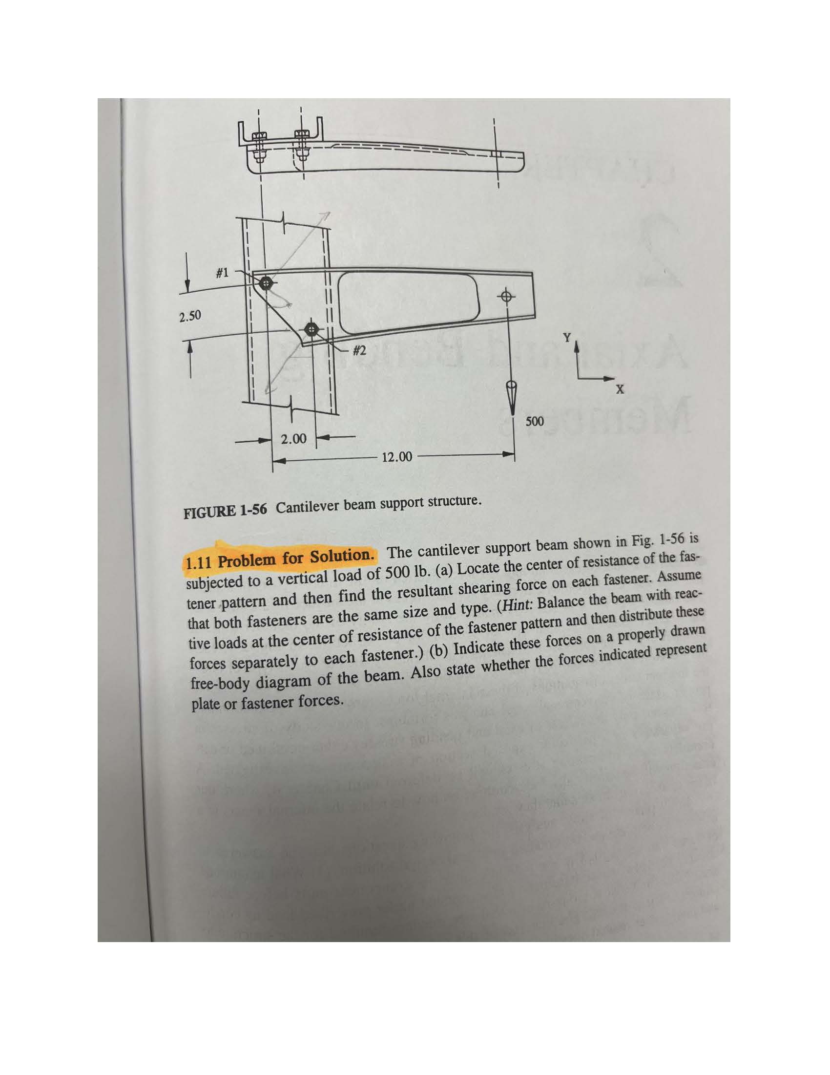
2.50 #1 #2 2.00 12.00 500 FIGURE 1-56 Cantilever beam support structure. 1.11 Problem for Solution. The cantilever support beam shown in Fig. 1-56

2.50 #1 #2 2.00 12.00 500 FIGURE 1-56 Cantilever beam support structure. 1.11 Problem for Solution. The cantilever support beam shown in Fig. 1-56 is subjected to a vertical load of 500 lb. (a) Locate the center of resistance of the fas- tener pattern and then find the resultant shearing force on each fastener. Assume that both fasteners are the same size and type. (Hint: Balance the beam with reac- tive loads at the center of resistance of the fastener pattern and then distribute these forces separately to each fastener.) (b) Indicate these forces on a properly drawn free-body diagram of the beam. Also state whether the forces indicated represent plate or fastener forces.
Step by Step Solution
There are 3 Steps involved in it
Step: 1

Get Instant Access to Expert-Tailored Solutions
See step-by-step solutions with expert insights and AI powered tools for academic success
Step: 2

Step: 3

Ace Your Homework with AI
Get the answers you need in no time with our AI-driven, step-by-step assistance
Get Started


