Answered step by step
Verified Expert Solution
Question
1 Approved Answer
2X 4XR 2X 3 + 2 of 3 | CD 4X B. 3 C. -2X 1-2X A. CENTERED 3 83 2XR 2x 24x7 2X


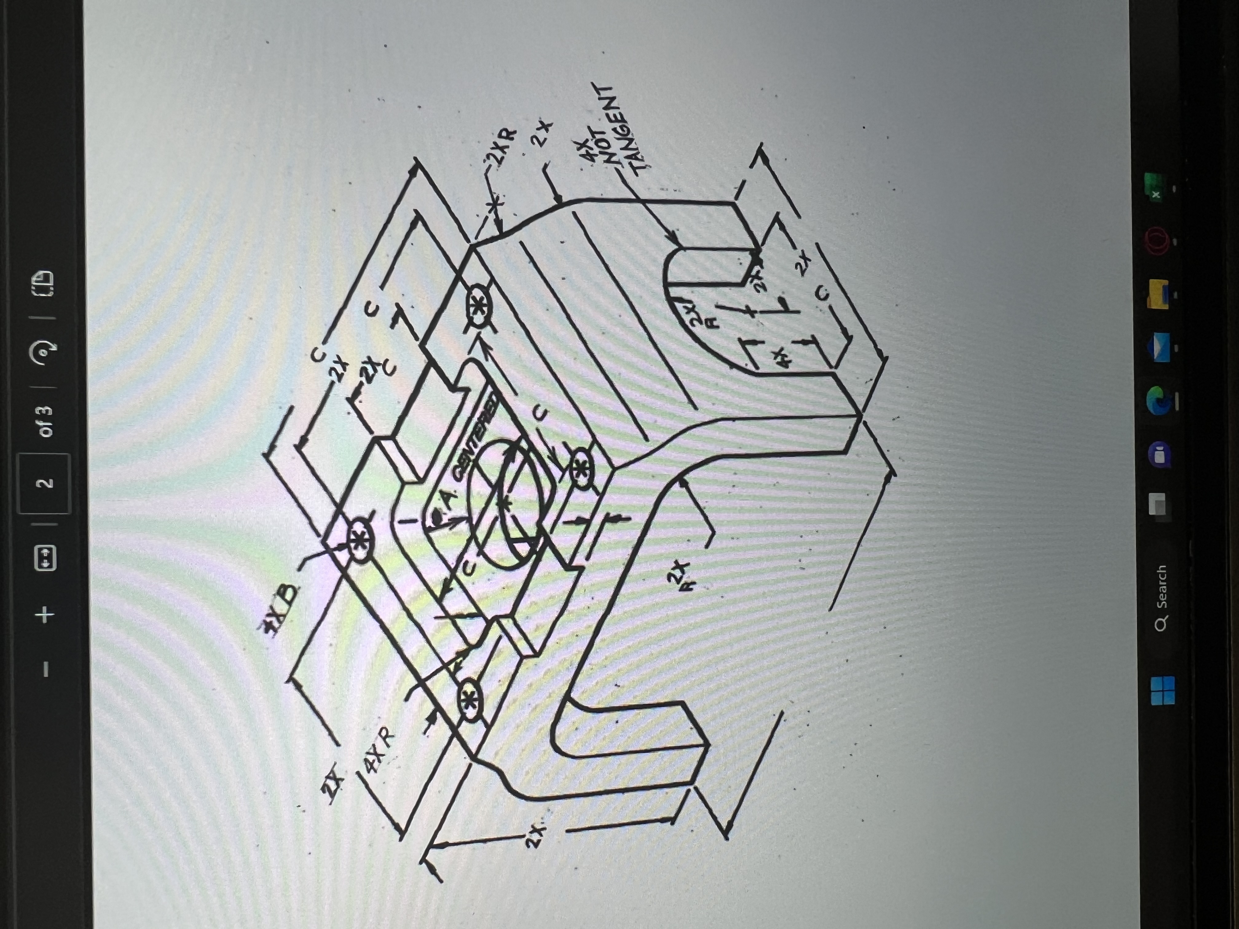
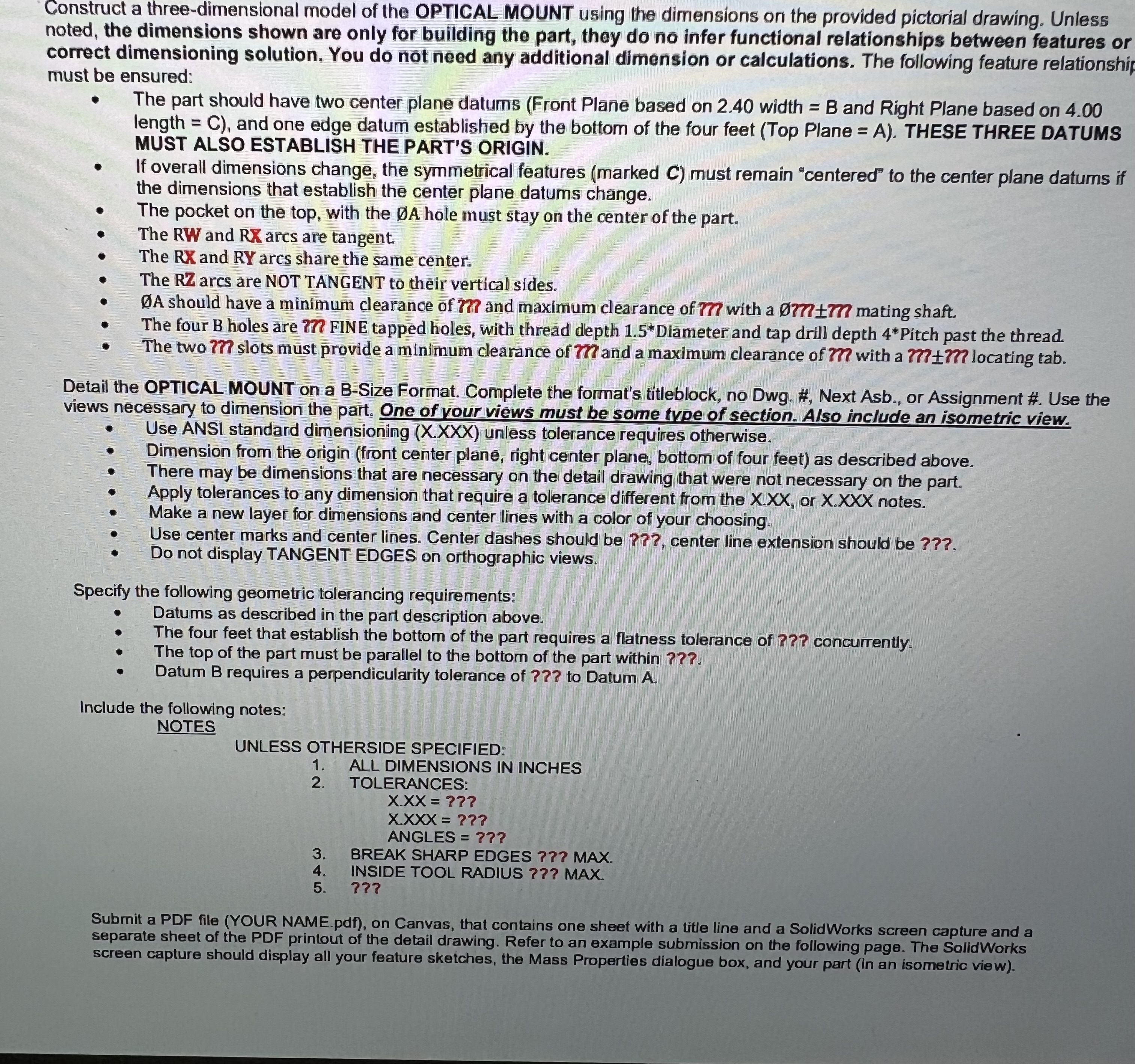
2X 4XR 2X 3 + 2 of 3 | CD 4X B. 3 C. -2X 1-2X A. CENTERED 3 83 2XR 2x 24x7 2X 4 4X NOT TANGENT 4X Q Search X Construct a three-dimensional model of the OPTICAL MOUNT using the dimensions on the provided pictorial drawing. Unless noted, the dimensions shown are only for building the part, they do no infer functional relationships between features or correct dimensioning solution. You do not need any additional dimension or calculations. The following feature relationship must be ensured: The part should have two center plane datums (Front Plane based on 2.40 width = B and Right Plane based on 4.00 length = C), and one edge datum established by the bottom of the four feet (Top Plane = A). THESE THREE DATUMS MUST ALSO ESTABLISH THE PART'S ORIGIN. If overall dimensions change, the symmetrical features (marked C) must remain "centered" to the center plane datums if the dimensions that establish the center plane datums change. The pocket on the top, with the A hole must stay on the center of the The RW and RX arcs are tangent. The RX and RY arcs share the same center. The RZ arcs are NOT TANGENT to their vertical sides. part. A should have a minimum clearance of ??? and maximum clearance of ??? with a 0777+7?? mating shaft. The four B holes are ??? FINE tapped holes, with thread depth 1.5*Diameter and tap drill depth 4*Pitch past the thread. The two ??? slots must provide a minimum clearance of ??? and a maximum clearance of ??? with a ?????? locating tab. Detail the OPTICAL MOUNT on a B-Size Format. Complete the format's titleblock, no Dwg. #, Next Asb., or Assignment #. Use the views necessary to dimension the part. One of your views must be some type of section. Also include an isometric view. Use ANSI standard dimensioning (X.XXX) unless tolerance requires otherwise. Dimension from the origin (front center plane, right center plane, bottom of four feet) as described above. There may be dimensions that are necessary on the detail drawing that were not necessary on the part. Apply tolerances to any dimension that require a tolerance different from the X.XX, or X.XXX notes. Make a new layer for dimensions and center lines with a color of your choosing. Use center marks and center lines. Center dashes should be ???, center line extension should be ???. Do not display TANGENT EDGES on orthographic views. Specify the following geometric tolerancing requirements: Datums as described in the part description above. The four feet that establish the bottom of the part requires a flatness tolerance of ??? concurrently. The top of the part must be parallel to the bottom of the part within ???. Datum B requires a perpendicularity tolerance of ??? to Datum A. Include the following notes: NOTES UNLESS OTHERSIDE SPECIFIED: 1. ALL DIMENSIONS IN INCHES TOLERANCES: 2. 3. 4. 5. XXX= ??? X.XXX = ??? ANGLES = ??? BREAK SHARP EDGES ??? MAX. INSIDE TOOL RADIUS ??? MAX. ??? Submit a PDF file (YOUR NAME.pdf), on Canvas, that contains one sheet with a title line and a SolidWorks screen capture and a separate sheet of the PDF printout of the detail drawing. Refer to an example submission on the following page. The SolidWorks screen capture should display all your feature sketches, the Mass Properties dialogue box, and your part (in an isometric view).
Step by Step Solution
There are 3 Steps involved in it
Step: 1

Get Instant Access to Expert-Tailored Solutions
See step-by-step solutions with expert insights and AI powered tools for academic success
Step: 2

Step: 3

Ace Your Homework with AI
Get the answers you need in no time with our AI-driven, step-by-step assistance
Get Started


