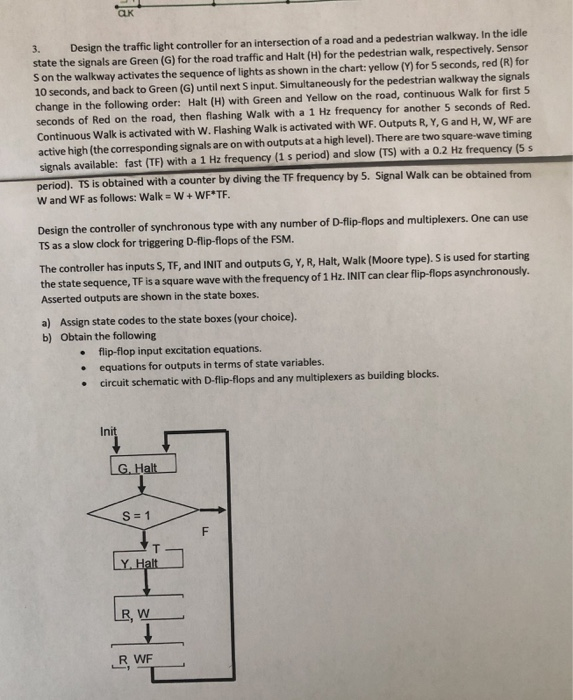
3. Design the traffic light controller for an intersection of a road and a pedestrian walkway. In the idle state the signals are Green (G) for the road traffic and Halt (H) for the pedestrian walk, respectively. Sensor Son the walkway activates the sequence of lights as shown in the chart: yellow (Y) for 5 seconds, red (R) for 10 seconds, and back to Green (G) until next Sinput. Simultaneously for the pedestrian walkway the signals change in the following order: Halt (H) with Green and Yellow on the road, continuous Walk for first 5 seconds of Red on the road, then flashing Walk with a 1 Hz frequency for another 5 seconds of Red. Continuous Walk is activated with W. Flashing Walk is activated with WF. Outputs R, Y, G and H, W, WF are active high (the corresponding signals are on with outputs at a high level). There are two square-wave timing signals available: fast (TF) with a 1 Hz frequency (1 s period) and slow (TS) with a 0.2 Hz frequency (5 s period). TS is obtained with a counter by diving the TF frequency by 5. Signal Walk can be obtained from W and WF as follows: Walk = W + WF*TF. Design the controller of synchronous type with any number of D-flip-flops and multiplexers. One can use TS as a slow clock for triggering D-flip-flops of the FSM. The controller has inputs S, TF, and INIT and outputs G, Y, R, Halt, Walk (Moore type). S is used for starting the state sequence, TF is a square wave with the frequency of 1 Hz. INIT can clear flip-flops asynchronously. Asserted outputs are shown in the state boxes. a) Assign state codes to the state boxes (your choice). b) Obtain the following flip-flop input excitation equations. equations for outputs in terms of state variables. circuit schematic with D-flip-flops and any multiplexers as building blocks. Init G. Halt S = 1 F Y Halt RW RWF 3. Design the traffic light controller for an intersection of a road and a pedestrian walkway. In the idle state the signals are Green (G) for the road traffic and Halt (H) for the pedestrian walk, respectively. Sensor Son the walkway activates the sequence of lights as shown in the chart: yellow (Y) for 5 seconds, red (R) for 10 seconds, and back to Green (G) until next Sinput. Simultaneously for the pedestrian walkway the signals change in the following order: Halt (H) with Green and Yellow on the road, continuous Walk for first 5 seconds of Red on the road, then flashing Walk with a 1 Hz frequency for another 5 seconds of Red. Continuous Walk is activated with W. Flashing Walk is activated with WF. Outputs R, Y, G and H, W, WF are active high (the corresponding signals are on with outputs at a high level). There are two square-wave timing signals available: fast (TF) with a 1 Hz frequency (1 s period) and slow (TS) with a 0.2 Hz frequency (5 s period). TS is obtained with a counter by diving the TF frequency by 5. Signal Walk can be obtained from W and WF as follows: Walk = W + WF*TF. Design the controller of synchronous type with any number of D-flip-flops and multiplexers. One can use TS as a slow clock for triggering D-flip-flops of the FSM. The controller has inputs S, TF, and INIT and outputs G, Y, R, Halt, Walk (Moore type). S is used for starting the state sequence, TF is a square wave with the frequency of 1 Hz. INIT can clear flip-flops asynchronously. Asserted outputs are shown in the state boxes. a) Assign state codes to the state boxes (your choice). b) Obtain the following flip-flop input excitation equations. equations for outputs in terms of state variables. circuit schematic with D-flip-flops and any multiplexers as building blocks. Init G. Halt S = 1 F Y Halt RW RWF


