Answered step by step
Verified Expert Solution
Question
1 Approved Answer
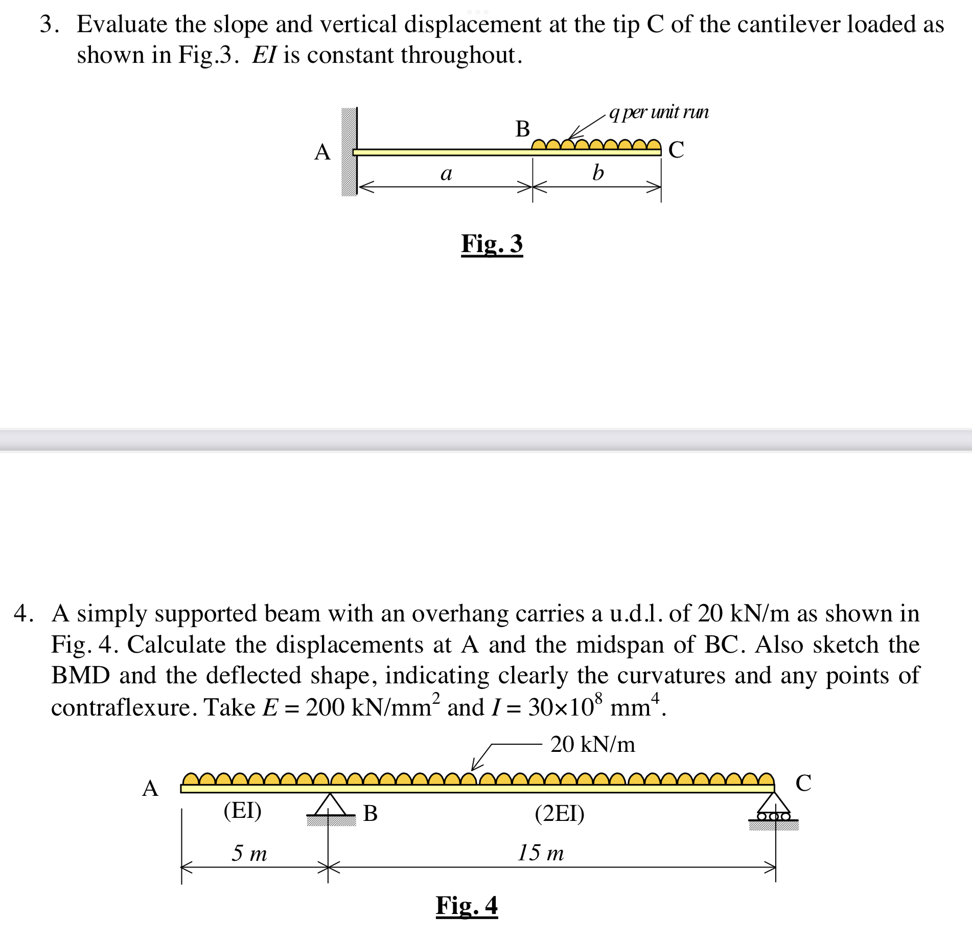
3. Evaluate the slope and vertical displacement at the tip C of the cantilever loaded as shown in Fig.3. El is constant throughout. q


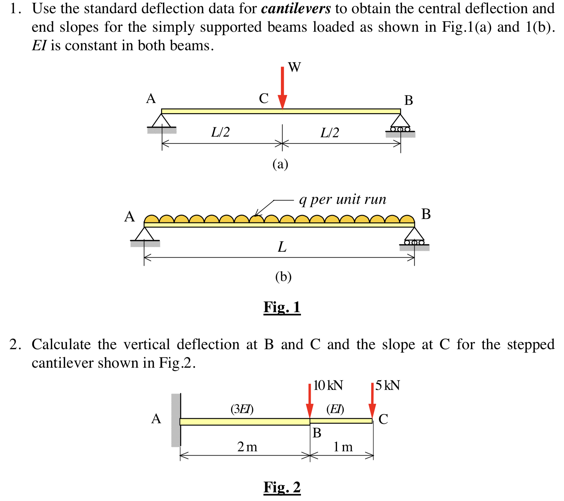
3. Evaluate the slope and vertical displacement at the tip C of the cantilever loaded as shown in Fig.3. El is constant throughout. q per unit run B A b Fig. 3 4. A simply supported beam with an overhang carries a u.d.l. of 20 kN/m as shown in Fig. 4. Calculate the displacements at A and the midspan of BC. Also sketch the BMD and the deflected shape, indicating clearly the curvatures and any points of contraflexure. Take E = 200 kN/mm and I = 30108 mm. A (EI) B 5 m 20 kN/m (2EI) 15 m Fig. 4 C 1. Use the standard deflection data for cantilevers to obtain the central deflection and end slopes for the simply supported beams loaded as shown in Fig.1(a) and 1(b). El is constant in both beams. A L/2 C W B A L/2 000 (a) q per unit run B L (b) Fig. 1 2. Calculate the vertical deflection at B and C and the slope at C for the stepped cantilever shown in Fig.2. 10 kN 5 kN (3EI) (EI) A C B 2m 1 m Fig. 2
Step by Step Solution
There are 3 Steps involved in it
Step: 1

Get Instant Access to Expert-Tailored Solutions
See step-by-step solutions with expert insights and AI powered tools for academic success
Step: 2

Step: 3

Ace Your Homework with AI
Get the answers you need in no time with our AI-driven, step-by-step assistance
Get Started


