

Question: 3. Figure 4 shows a horizontal beam ABCD supported by am BE. The beam pin jointed to a rigid wall at A, and arm
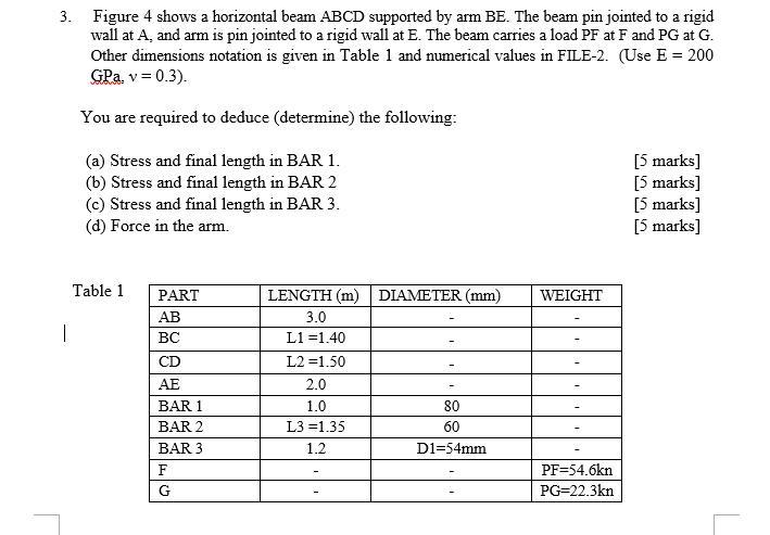
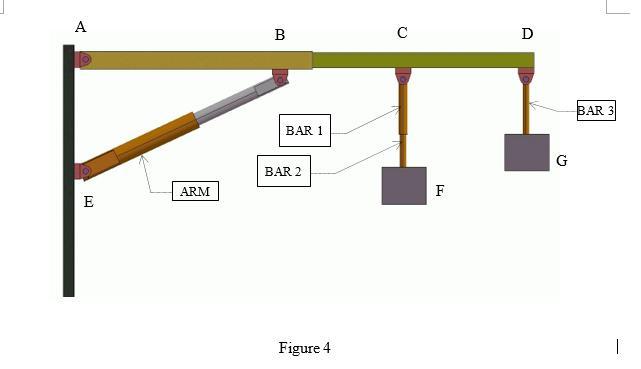
3. Figure 4 shows a horizontal beam ABCD supported by am BE. The beam pin jointed to a rigid wall at A, and arm is pin jointed to a rigid wall at E. The beam carries a load PF at F and PG at G. Other dimensions notation is given in Table 1 and numerical values in FILE-2. (Use E = 200 GPa. v = 0.3). You are required to deduce (determine) the following: (a) Stress and final length in BAR 1. (b) Stress and final length in BAR 2 (c) Stress and final length in BAR 3. (d) Force in the arm. [5 marks] [5 marks] [5 marks] [5 marks] Table 1 PART LENGTH (m) DIAMETER (mm) WEIGHT AB 3.0 L1 =1.40 CD L2 =1.50 AE 2.0 BAR 1 1.0 80 BAR 2 L3 =1.35 60 BAR 3 1.2 D1=54mm PF=54.6kn G PG=22.3kn A B D BAR 3 BAR 1 G BAR 2 ARM F E Figure 4
Step by Step Solution
3.50 Rating (153 Votes )
There are 3 Steps involved in it
To solve this problem we need to determine the stress and final length in each of the bars and the force in the arm Well proceed step by step Given Da... View full answer

Get step-by-step solutions from verified subject matter experts