Question
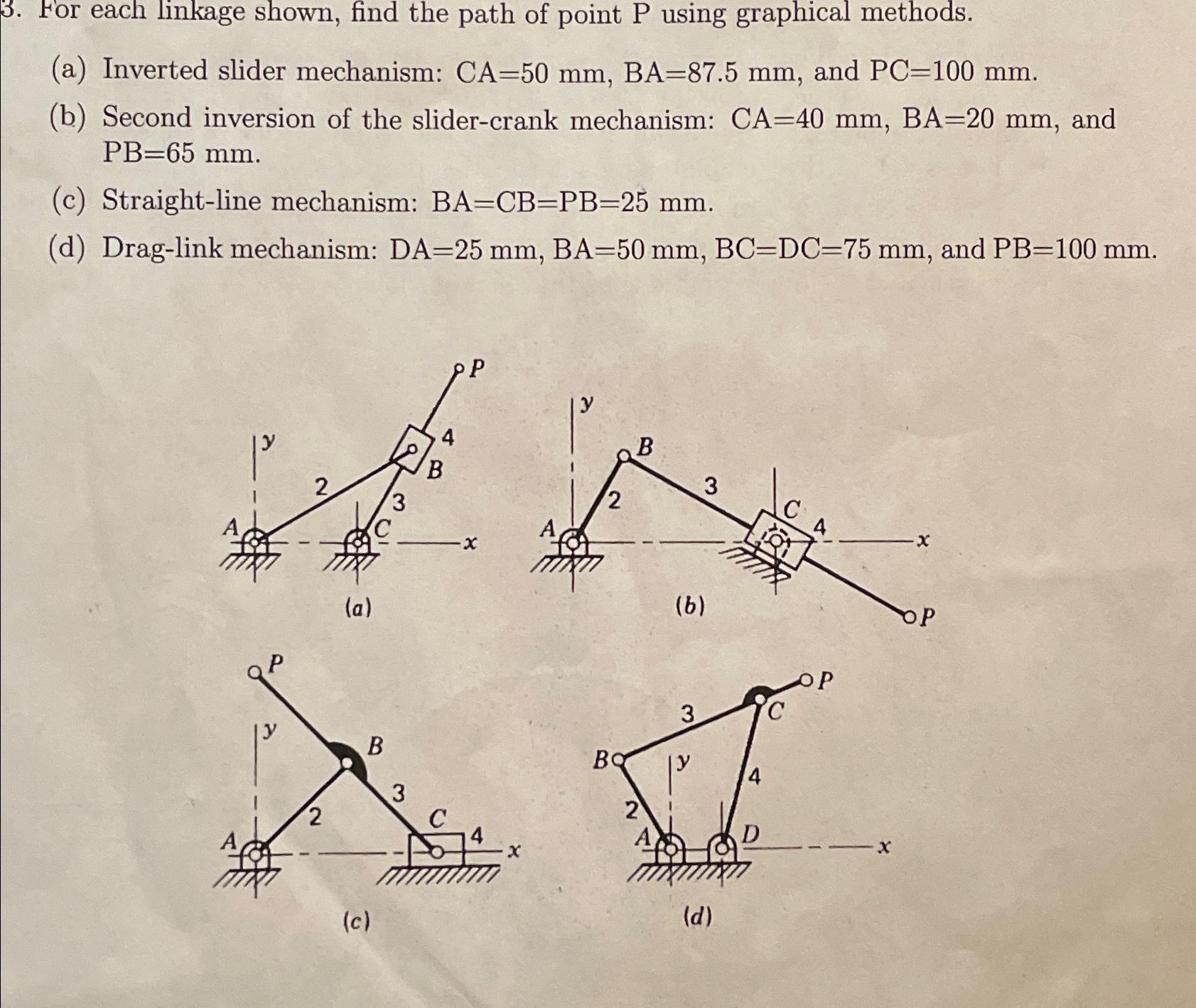
3. For each linkage shown, find the path of point P using graphical methods. (a) Inverted slider mechanism: CA=50 mm, BA-87.5 mm, and PC=100

3. For each linkage shown, find the path of point P using graphical methods. (a) Inverted slider mechanism: CA=50 mm, BA-87.5 mm, and PC=100 mm. (b) Second inversion of the slider-crank mechanism: CA=40 mm, BA=20 mm, and PB=65 mm. (c) Straight-line mechanism: BA=CB=PB-25 mm. (d) Drag-link mechanism: DA=25 mm, BA=50 mm, BC=DC-75 mm, and PB-100 mm. 2 2 (a) B (c) 3 B C P 4 2 Bo B 2 3 (b) 3 (d) 4 D A OP
Step by Step Solution
3.37 Rating (163 Votes )
There are 3 Steps involved in it
Step: 1
Answer STEPS 1 Draw the fixed links first 2 Draw the circle of the rad...
Get Instant Access to Expert-Tailored Solutions
See step-by-step solutions with expert insights and AI powered tools for academic success
Step: 2

Step: 3

Ace Your Homework with AI
Get the answers you need in no time with our AI-driven, step-by-step assistance
Get StartedRecommended Textbook for
Vector Mechanics for Engineers Statics and Dynamics
Authors: Ferdinand Beer, E. Russell Johnston, Jr., Elliot Eisenberg, William Clausen, David Mazurek, Phillip Cornwell
8th Edition
73212229, 978-0073212227
Students also viewed these Mechanical Engineering questions
Question
Answered: 1 week ago
Question
Answered: 1 week ago
Question
Answered: 1 week ago
Question
Answered: 1 week ago
Question
Answered: 1 week ago
Question
Answered: 1 week ago
Question
Answered: 1 week ago
Question
Answered: 1 week ago
Question
Answered: 1 week ago
Question
Answered: 1 week ago
Question
Answered: 1 week ago
Question
Answered: 1 week ago
Question
Answered: 1 week ago
Question
Answered: 1 week ago
Question
Answered: 1 week ago
Question
Answered: 1 week ago
Question
Answered: 1 week ago
Question
Answered: 1 week ago
Question
Answered: 1 week ago
Question
Answered: 1 week ago
Question
Answered: 1 week ago
View Answer in SolutionInn App


