Answered step by step
Verified Expert Solution
Question
1 Approved Answer
3. Supercavitating Vehicle Control Supercavitating vehicles can travel underwater at extremely high speeds. The increase in speed is accomplished through a dramatic reduction in

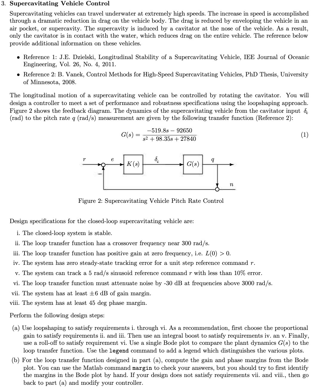
3. Supercavitating Vehicle Control Supercavitating vehicles can travel underwater at extremely high speeds. The increase in speed is accomplished through a dramatic reduction in drag on the vehicle body. The drag is reduced by enveloping the vehicle in an air pocket, or supercavity. The supercavity is induced by a cavitator at the nose of the vehicle. As a result, only the cavitator is in contact with the water, which reduces drag on the entire vehicle. The reference below provide additional information on these vehicles. Reference 1: J.E. Dzielski, Longitudinal Stability of a Supercavitating Vehicle, IEE Journal of Oceanic Engineering, Vol. 26, No. 4, 2011. Reference 2: B. Vanek, Control Methods for High-Speed Supercavitating Vehicles, PhD Thesis, University of Minnesota, 2008. The longitudinal motion of a supercavitating vehicle can be controlled by rotating the cavitator. You will design a controller to meet a set of performance and robustness specifications using the loopshaping approach. Figure 2 shows the feedback diagram. The dynamics of the supercavitating vehicle from the cavitator input & (rad) to the pitch rate q (rad/s) measurement are given by the following transfer function (Reference 2): -519.8s 92650 G(s)= $298.35s + 27840 r e 8 q K(s) G(s) n (1) Figure 2: Supercavitating Vehicle Pitch Rate Control Design specifications for the closed-loop supercavitating vehicle are: i. The closed-loop system is stable. ii. The loop transfer function has a crossover frequency near 300 rad/s. iii. The loop transfer function has positive gain at zero frequency, i.e. L(0) > 0. iv. The system has zero steady-state tracking error for a unit step reference command r. v. The system can track a 5 rad/s sinusoid reference command r with less than 10% error. vi. The loop transfer function must attenuate noise by -30 dB at frequencies above 3000 rad/s. vii. The system has at least 6 dB of gain margin. viii. The system has at least 45 deg phase margin. Perform the following design steps: (a) Use loopshaping to satisfy requirements i. through vi. As a recommendation, first choose the proportional gain to satisfy requirements ii. and iii. Then use an integral boost to satisfy requirements iv. an v. Finally, use a roll-off to satisfy requirement vi. Use a single Bode plot to compare the plant dynamics G(s) to the loop transfer function. Use the legend command to add a legend which distinguishes the various plots. (b) For the loop transfer function designed in part (a), compute the gain and phase margins from the Bode plot. You can use the Matlab command margin to check your answers, but you should try to first identify the margins in the Bode plot by hand. If your design does not satisfy requirements vii. and viii., then go back to part (a) and modify your controller.
Step by Step Solution
There are 3 Steps involved in it
Step: 1

Get Instant Access to Expert-Tailored Solutions
See step-by-step solutions with expert insights and AI powered tools for academic success
Step: 2

Step: 3

Ace Your Homework with AI
Get the answers you need in no time with our AI-driven, step-by-step assistance
Get Started


