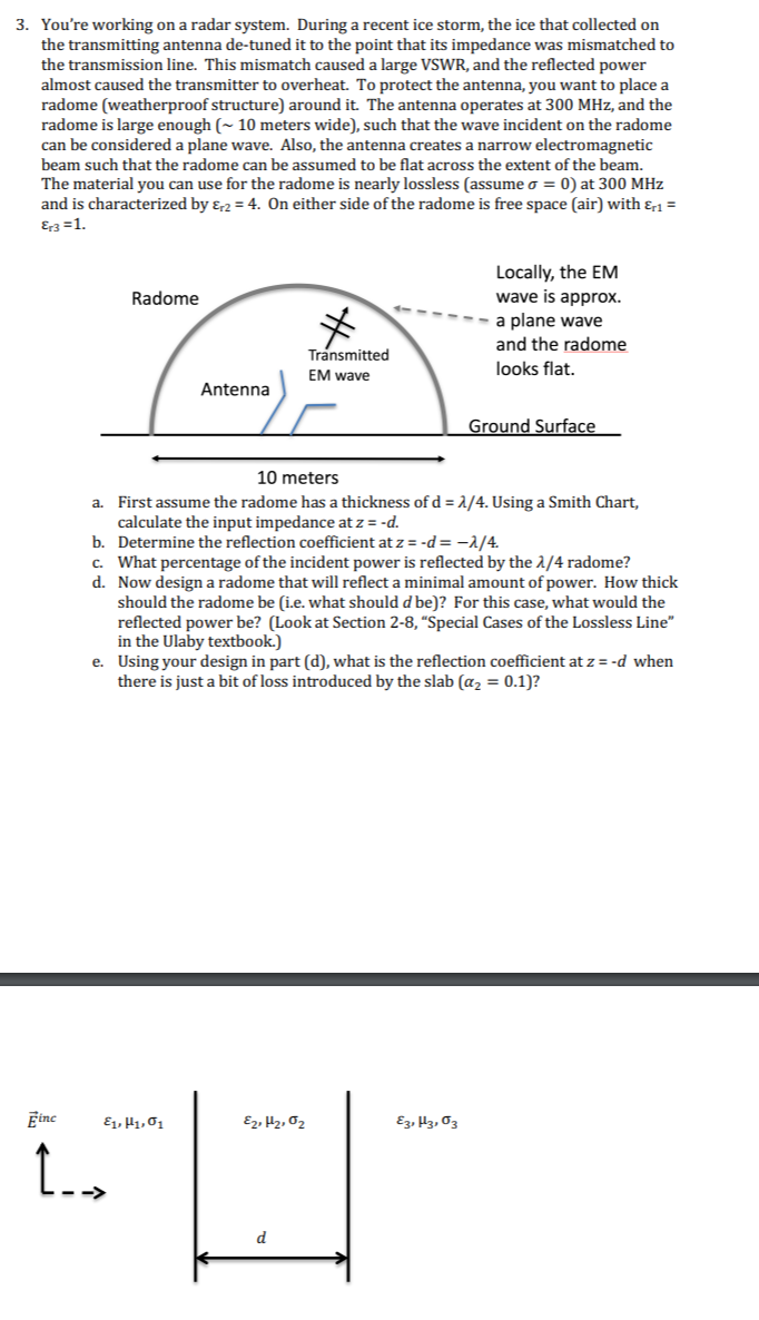
Question: 3. You're working on a radar system. During a recent ice storm, the ice that collected on the transmitting antenna de-tuned it to the point

3. You're working on a radar system. During a recent ice storm, the ice that collected on the transmitting antenna de-tuned it to the point that its impedance was mismatched to the transmission line. This mismatch caused a large VSWR, and the reflected power almost caused the transmitter to overheat. To protect the antenna, you want to place a radome (weatherproof structure) around it. The antenna operates at 300 MHz, and the radome is large enough ( 10 meters wide), such that the wave incident on the radome can be considered a plane wave. Also, the antenna creates a narrow electromagnetic beam such that the radome can be assumed to be flat across the extent of the beam. The material you can use for the radome is nearly lossless (assume o =0) at 300 MHz and is characterized by &r2 = 4. On either side of the radome is free space (air) with 1 = Er3=1. Radome Locally, the EM wave is approx. a plane wave and the radome looks flat. Transmitted EM wave Antenna Ground Surface 10 meters a. First assume the radome has a thickness of d = 1/4. Using a Smith Chart, calculate the input impedance at z=-d. b. Determine the reflection coefficient at z=-d=-1/4. c. What percentage of the incident power is reflected by the 1/4 radome? d. Now design a radome that will reflect a minimal amount of power. How thick should the radome be i.e. what should d be)? For this case, what would the reflected power be? (Look at Section 2-8, "Special Cases of the Lossless Line" in the Ulaby textbook.) e. Using your design in part (d), what is the reflection coefficient at z=-d when there is just a bit of loss introduced by the slab (az = 0.1)? Einc E1, H1,01 E2, H2,02 Ez, Hz,03 I. d 3. You're working on a radar system. During a recent ice storm, the ice that collected on the transmitting antenna de-tuned it to the point that its impedance was mismatched to the transmission line. This mismatch caused a large VSWR, and the reflected power almost caused the transmitter to overheat. To protect the antenna, you want to place a radome (weatherproof structure) around it. The antenna operates at 300 MHz, and the radome is large enough ( 10 meters wide), such that the wave incident on the radome can be considered a plane wave. Also, the antenna creates a narrow electromagnetic beam such that the radome can be assumed to be flat across the extent of the beam. The material you can use for the radome is nearly lossless (assume o =0) at 300 MHz and is characterized by &r2 = 4. On either side of the radome is free space (air) with 1 = Er3=1. Radome Locally, the EM wave is approx. a plane wave and the radome looks flat. Transmitted EM wave Antenna Ground Surface 10 meters a. First assume the radome has a thickness of d = 1/4. Using a Smith Chart, calculate the input impedance at z=-d. b. Determine the reflection coefficient at z=-d=-1/4. c. What percentage of the incident power is reflected by the 1/4 radome? d. Now design a radome that will reflect a minimal amount of power. How thick should the radome be i.e. what should d be)? For this case, what would the reflected power be? (Look at Section 2-8, "Special Cases of the Lossless Line" in the Ulaby textbook.) e. Using your design in part (d), what is the reflection coefficient at z=-d when there is just a bit of loss introduced by the slab (az = 0.1)? Einc E1, H1,01 E2, H2,02 Ez, Hz,03 I. d
Step by Step Solution
There are 3 Steps involved in it

Get step-by-step solutions from verified subject matter experts


