Answered step by step
Verified Expert Solution
Question
1 Approved Answer
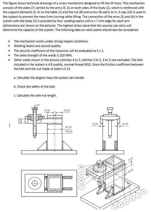
The figure shows technical drawings of a screw mechanism designed to lift the M mass. This mechanism consists of the plate (7) carried by

The figure shows technical drawings of a screw mechanism designed to lift the M mass. This mechanism consists of the plate (7) carried by the arms (5, 6) on both sides of the body (2), which is reinforced with the support elements (3, 4) on the table (1) and the nut (8) and screw (9) parts on it. A cap (10) is used in the system to prevent the mass from turning while lifting. The connection of the arms (5) and (6) in the system with the body (2) is provided by four welding seams with a = 7 mm edge for each arm (dimensions are shown on the picture). The highest stress value that the sources can carry will determine the capacity of the system. The following data on weld seams should also be considered: The mechanism works under strong impact conditions. Welding Seams are second quality. The security coefficient of the resources will be evaluated as S = 1. The yield strength of the welds is 320 MPa. Other welds shown in the picture (stitches 4 to 2; stitches 3 to 2, 2 to 1) are excluded. The bolt included in the system is 4.8 quality, normal thread M10. Since the friction coefficient between the bolt and the nut made of steel is 0.15 a. Calculate the largest mass the system can handle. b. Check the safety of the bolt. c. Calculate the safe nut length. 35,00 35,00 80,00 108,00 10 12,00 12,00 200,00 200000
Step by Step Solution
★★★★★
3.45 Rating (158 Votes )
There are 3 Steps involved in it
Step: 1
a b We calculate th...
Get Instant Access to Expert-Tailored Solutions
See step-by-step solutions with expert insights and AI powered tools for academic success
Step: 2

Step: 3

Document Format ( 2 attachments)
635db96e9dfe5_178333.pdf
180 KBs PDF File
635db96e9dfe5_178333.docx
120 KBs Word File
Ace Your Homework with AI
Get the answers you need in no time with our AI-driven, step-by-step assistance
Get Started


