Answered step by step
Verified Expert Solution
Question
1 Approved Answer
4) Link layer (and network layer) addressing and forwarding (3 pts) Consider the figure below. The IP and MAC addresses are shown for nodes A,
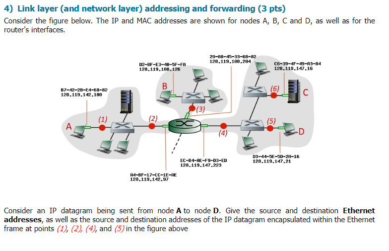
4) Link layer (and network layer) addressing and forwarding (3 pts) Consider the figure below. The IP and MAC addresses are shown for nodes A, B, C and D, as well as for the router's interfaces. 29-88-49-39-68-82 128.119.108.204 D2-BF-E3-40-5F-FA 128.119.188.126 C6-39-4F-49-A3-84 128.119.147.16 B7-42-28-E4-68-82 128.119.142.100 EC-B4-AE-F9-03-ED 128.119.147.223 03-44-5E-50-2A-16 128.119.147.21 A4-BF-17-CC-1E-RE 128.119.142.97 Consider an IP datagram being sent from node A to node D. Give the source and destination Ethernet addresses, as well as the source and destination addresses of the IP datagram encapsulated within the Ethernet frame at points (1), (2), (4), and (5) in the figure above 4) Link layer (and network layer) addressing and forwarding (3 pts) Consider the figure below. The IP and MAC addresses are shown for nodes A, B, C and D, as well as for the router's interfaces. 29-88-49-39-68-82 128.119.108.204 D2-BF-E3-40-5F-FA 128.119.188.126 C6-39-4F-49-A3-84 128.119.147.16 B7-42-28-E4-68-82 128.119.142.100 EC-B4-AE-F9-03-ED 128.119.147.223 03-44-5E-50-2A-16 128.119.147.21 A4-BF-17-CC-1E-RE 128.119.142.97 Consider an IP datagram being sent from node A to node D. Give the source and destination Ethernet addresses, as well as the source and destination addresses of the IP datagram encapsulated within the Ethernet frame at points (1), (2), (4), and (5) in the figure above
Step by Step Solution
There are 3 Steps involved in it
Step: 1
Get Instant Access to Expert-Tailored Solutions
See step-by-step solutions with expert insights and AI powered tools for academic success
Step: 2
Step: 3
Ace Your Homework with AI
Get the answers you need in no time with our AI-driven, step-by-step assistance
Get Started