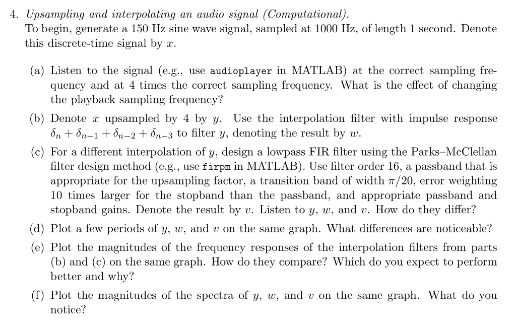
4. Upsampling and interpolating an audio signal (Computational). To begin, generate a 150 Hz sine wave signal, sampled at 1000 Hz, of length 1 second. Denote this discrete-time signal by x. (a) Listen to the signal (e.g., use audioplayer in MATLAB) at the correct sampling fre- quency and at 4 times the correct sampling frequency. What is the effect of changing the playback sampling frequency? (b) Denote c upsampled by 4 by y. Use the interpolation filter with impulse response dn + dn-1 + dn2 + dn3 to filter y, denoting the result by w. For a different interpolation of y, design a lowpass FIR filter using the Parks-McClellan filter design method (e.g., use firpm in MATLAB). Use filter order 16, a passband that is appropriate for the upsampling factor, a transition band of width 7/20, error weighting 10 times larger for the stopband than the passband, and appropriate passband and stopband gains. Denote the result by v. Listen to y, w, and v. How do they differ? (d) Plot a few periods of y, w, and v on the same graph. What differences are noticeable? (e) Plot the magnitudes of the frequency responses of the interpolation filters from parts (b) and (c) on the same graph. How do they compare? Which do you expect to perform better and why? (f) Plot the magnitudes of the spectra of y, w, and v on the same graph. What do you notice? 4. Upsampling and interpolating an audio signal (Computational). To begin, generate a 150 Hz sine wave signal, sampled at 1000 Hz, of length 1 second. Denote this discrete-time signal by x. (a) Listen to the signal (e.g., use audioplayer in MATLAB) at the correct sampling fre- quency and at 4 times the correct sampling frequency. What is the effect of changing the playback sampling frequency? (b) Denote c upsampled by 4 by y. Use the interpolation filter with impulse response dn + dn-1 + dn2 + dn3 to filter y, denoting the result by w. For a different interpolation of y, design a lowpass FIR filter using the Parks-McClellan filter design method (e.g., use firpm in MATLAB). Use filter order 16, a passband that is appropriate for the upsampling factor, a transition band of width 7/20, error weighting 10 times larger for the stopband than the passband, and appropriate passband and stopband gains. Denote the result by v. Listen to y, w, and v. How do they differ? (d) Plot a few periods of y, w, and v on the same graph. What differences are noticeable? (e) Plot the magnitudes of the frequency responses of the interpolation filters from parts (b) and (c) on the same graph. How do they compare? Which do you expect to perform better and why? (f) Plot the magnitudes of the spectra of y, w, and v on the same graph. What do you notice


