Answered step by step
Verified Expert Solution
Question
1 Approved Answer
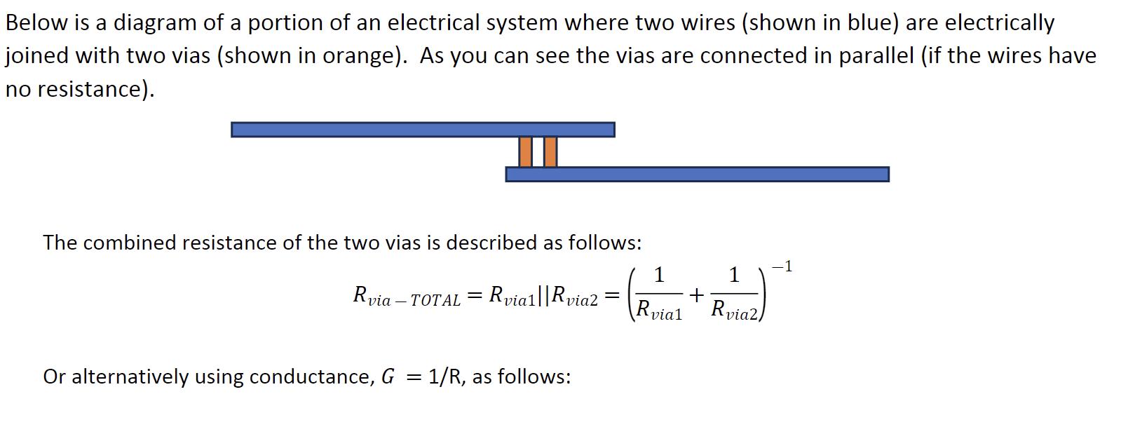
Below is a diagram of a portion of an electrical system where two wires (shown in blue) are electrically joined with two vias (shown


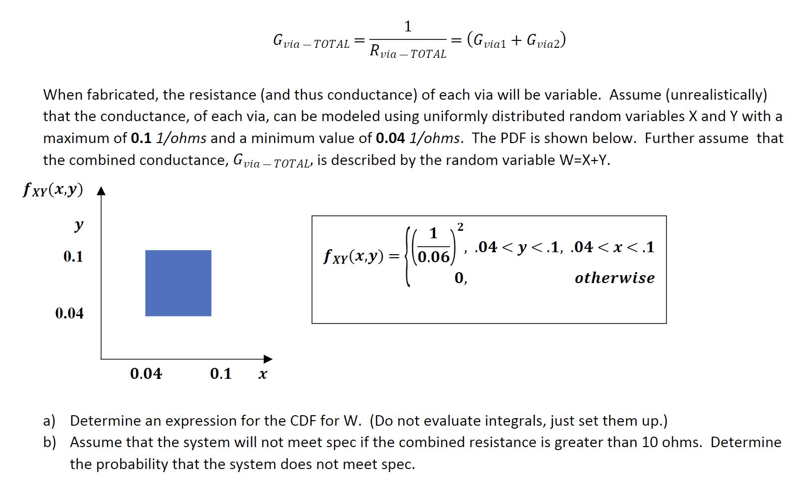
Below is a diagram of a portion of an electrical system where two wires (shown in blue) are electrically joined with two vias (shown in orange). As you can see the vias are connected in parallel (if the wires have no resistance). The combined resistance of the two vias is described as follows: Ruta:||PRvia2 = (Rytal R + Rvia-T via - TOTAL - Or alternatively using conductance, G = 1/R, as follows: 1 vial Rvia2) -1 y 0.1 0.04 0.04 0.1 Gvia TOTAL X Rvia- When fabricated, the resistance (and thus conductance) of each via will be variable. Assume (unrealistically) that the conductance, of each via, can be modeled using uniformly distributed random variables X and Y with a maximum of 0.1 1/ohms and a minimum value of 0.04 1/ohms. The PDF is shown below. Further assume that the combined conductance, Gvia - TOTAL, is described by the random variable W=X+Y. fxx(x,y) 1 via- TOTAL = fxx(x,y) = 0.06 (Gvia1 + Gvia2) 2 ) 0, .04y
Step by Step Solution
★★★★★
3.51 Rating (151 Votes )
There are 3 Steps involved in it
Step: 1
a Determine an expression for the CDF for W The CDF for W denoted as FWw represents the probability ...
Get Instant Access to Expert-Tailored Solutions
See step-by-step solutions with expert insights and AI powered tools for academic success
Step: 2

Step: 3

Ace Your Homework with AI
Get the answers you need in no time with our AI-driven, step-by-step assistance
Get Started


