Question: // 4.18b: flopr_sync // synchronously resettable flip flop module flopr(input logic clk, input logic reset, input logic [3:0] d, output logic [3:0] q); // synchronous

![clk, input logic reset, input logic [3:0] d, output logic [3:0] q);](https://dsd5zvtm8ll6.cloudfront.net/si.experts.images/questions/2024/09/66f0db7d1f485_86066f0db7cb820c.jpg)
// 4.18b: flopr_sync // synchronously resettable flip flop
module flopr(input logic clk, input logic reset, input logic [3:0] d, output logic [3:0] q);
// synchronous reset always_ff @(posedge clk) if (reset) q
// 4.24: sevenseg
module sevenseg(input logic [3:0] data, output logic [6:0] segments);
always_comb case (data) // abc_defg 0: segments = 7'b111_1110; 1: segments = 7'b011_0000; 2: segments = 7'b110_1101; 3: segments = 7'b111_1001; 4: segments = 7'b011_0011; 5: segments = 7'b101_1011; 6: segments = 7'b101_1111; 7: segments = 7'b111_0000; 8: segments = 7'b111_1111; 9: segments = 7'b111_0011; default: segments = 7'b000_0000; endcase endmodule
// 4.30: divideby3FSM
module divideby3FSM(input logic clk, input logic reset, output logic q);
typedef enum logic [1:0] {S0, S1, S2} statetype; statetype state, nextstate;
// state register always_ff @(posedge clk, posedge reset) if (reset) state
// next state logic always_comb case (state) S0: nextstate = S1; S1: nextstate = S2; S2: nextstate = S0; default: nextstate = S0; endcase
// output logic assign q = (state == S0); endmodule
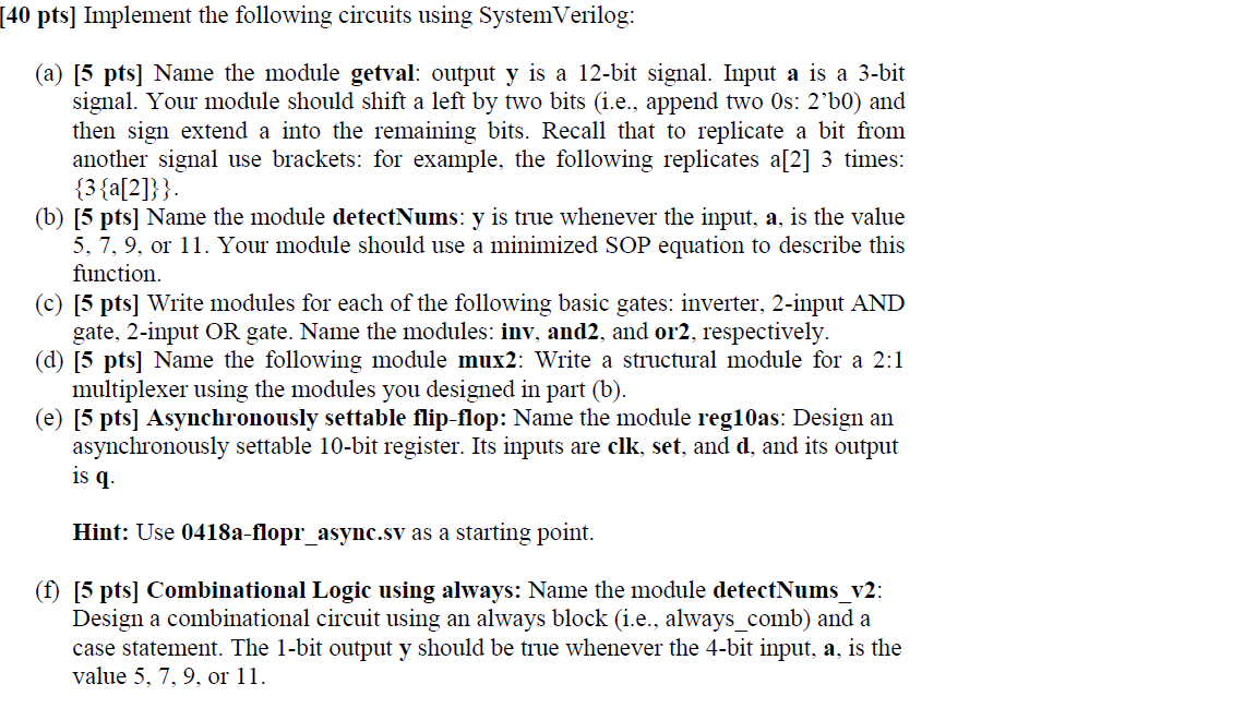
(a) 5 pts] Name the module getval: output y is a 12-bit signal. Input a is a 3-bit signal. Your module should shift a left by two bits (i.e., append two 0s: 2'b0) and then sign extend a into the remaining bits. Recall that to replicate a bit from another signal use brackets: for example, the following replicates a[2] 3 times: {3{a[2]}} (b) [5 pts] Name the module detectNums: y is true whenever the input, a, is the value 5,7,9, or 11 . Your module should use a minimized SOP equation to describe this function. (c) 55 pts] Write modules for each of the following basic gates: inverter, 2-input AND gate, 2-input OR gate. Name the modules: inv, and2, and or 2, respectively. (d) 5 pts] Name the following module mux2: Write a structural module for a 2:1 multiplexer using the modules you designed in part (b). (e) [5 pts] Asynchronously settable flip-flop: Name the module reg10as: Design an asynchronously settable 10-bit register. Its inputs are clk, set, and d, and its output is q. Hint: Use 0418a-flopr_async.sv as a starting point. (f) [5 pts] Combinational Logic using always: Name the module detectNums_v2: Design a combinational circuit using an always block (i.e., always_comb) and a case statement. The 1-bit output y should be true whenever the 4-bit input, a, is the value 5,7,9, or 11 Hint: Use 0424-sevenseg.sv as a starting point. [10 pts] FSM: Name the module fsm1: Design an FSM using SystemVerilog for the state transition diagram shown in Figure 1. The inputs are clk, reset, and w, and the outputs are a and b. Figure 1. State transition diagram for Exercises 2 and 3 Hint: You can use 0430-divideby3FSM.sv (or one of the other FSMs in the lecture notes) as a starting point. Remember that for FSMs, you go directly from the state transition diagram to writing the SystemVerilog (i.e., you do not write next state or output equations)
Step by Step Solution
There are 3 Steps involved in it

Get step-by-step solutions from verified subject matter experts


