Question
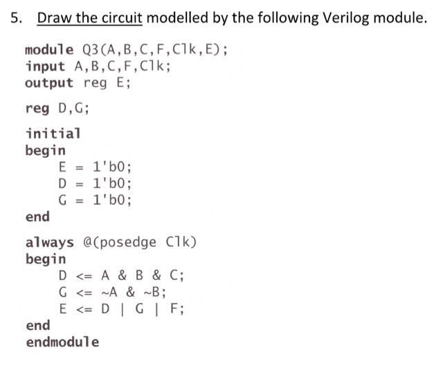
5. Draw the circuit modelled by the following Verilog module. module Q3 (A, B, C, F, C1k, E); input A, B, C, F, C1k;

5. Draw the circuit modelled by the following Verilog module. module Q3 (A, B, C, F, C1k, E); input A, B, C, F, C1k; output reg E; reg D, G; initial begin E = 1'b0; D = 1'b0; G = 1'b0; end always @(posedge C1k) begin D
Step by Step Solution
3.45 Rating (155 Votes )
There are 3 Steps involved in it
Step: 1
AS Inputs are A B C Output E these Statements ase non used always bl...
Get Instant Access to Expert-Tailored Solutions
See step-by-step solutions with expert insights and AI powered tools for academic success
Step: 2

Step: 3

Ace Your Homework with AI
Get the answers you need in no time with our AI-driven, step-by-step assistance
Get StartedRecommended Textbook for
Introduction to Data Mining
Authors: Pang Ning Tan, Michael Steinbach, Vipin Kumar
1st edition
321321367, 978-0321321367
Students also viewed these Electrical Engineering questions
Question
Answered: 1 week ago
Question
Answered: 1 week ago
Question
Answered: 1 week ago
Question
Answered: 1 week ago
Question
Answered: 1 week ago
Question
Answered: 1 week ago
Question
Answered: 1 week ago
Question
Answered: 1 week ago
Question
Answered: 1 week ago
Question
Answered: 1 week ago
Question
Answered: 1 week ago
Question
Answered: 1 week ago
Question
Answered: 1 week ago
Question
Answered: 1 week ago
Question
Answered: 1 week ago
Question
Answered: 1 week ago
Question
Answered: 1 week ago
Question
Answered: 1 week ago
Question
Answered: 1 week ago
Question
Answered: 1 week ago
Question
Answered: 1 week ago
Question
Answered: 1 week ago
Question
Answered: 1 week ago
View Answer in SolutionInn App


