Answered step by step
Verified Expert Solution
Question
1 Approved Answer
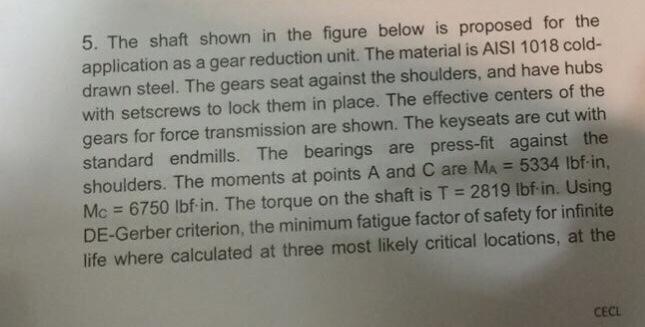
5. The shaft shown in the figure below is proposed for the application as a gear reduction unit. The material is AISI 1018 cold-


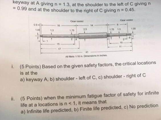
5. The shaft shown in the figure below is proposed for the application as a gear reduction unit. The material is AISI 1018 cold- drawn steel. The gears seat against the shoulders, and have hubs with setscrews to lock them in place. The effective centers of the gears for force transmission are shown. The keyseats are cut with standard endmills. The bearings are press-fit against the shoulders. The moments at points A and C are MA =5334 lbf-in, Mc =6750 lbf in. The torque on the shaft is T = 2819 lbf in. Using DE-Gerber criterion, the minimum fatigue factor of safety for infinite life where calculated at three most likely critical locations, at the CECL keyway at A giving n = 1.3, at the shoulder to the left of C giving n = 0.99 and at the shoulder to the right of C giving n = 0.45. Gear center 0.5- 1.00 1.3 1.75 15 17 41 Gear center 1.75 13 1.00 All fillets 1/16 in. Dimensions in inches. i. (5 Points) Based on the given safety factors, the critical locations is at the a) keyway A, b) shoulder - left of C, c) shoulder - right of C ii. (5 Points) when the minimum fatigue factor of safety for infinite life at a locations is n < 1, it means that a) Infinite life predicted, b) Finite life predicted, c) No prediction
Step by Step Solution
There are 3 Steps involved in it
Step: 1
Based on the provided information lets address each part of the question i Critical Locations Based on Given Safety Factors The critical locations for ...
Get Instant Access to Expert-Tailored Solutions
See step-by-step solutions with expert insights and AI powered tools for academic success
Step: 2

Step: 3

Ace Your Homework with AI
Get the answers you need in no time with our AI-driven, step-by-step assistance
Get Started


