Answered step by step
Verified Expert Solution
Question
1 Approved Answer
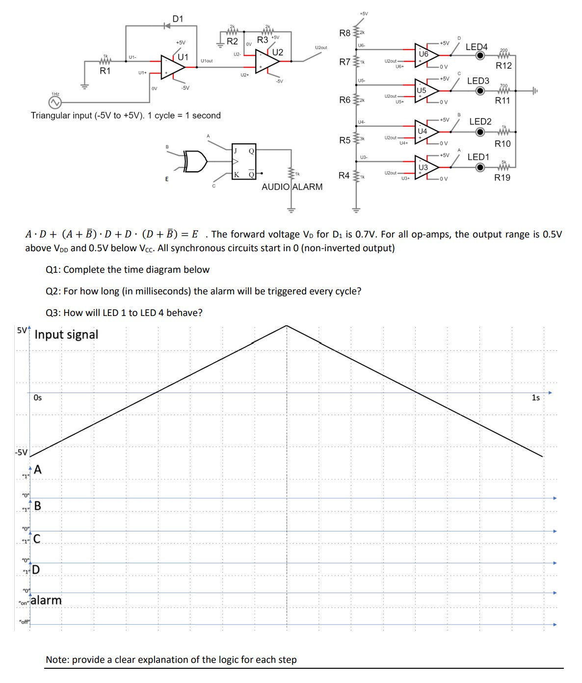
-5V 0 D ++ 10 D1 +5V +5V R2 OV U2- www R1 U1- U1 R3 +5V [U2 R8 +5V U2out LED4 U6 U1out

-5V "0" D ++ 10 D1 +5V +5V R2 OV U2- www R1 U1- U1 R3 +5V [U2 R8 +5V U2out LED4 U6 U1out R71k U2out- U6+ OV R12 U1+ U2+ -5V U5- +5V LED3 OV -5V U5 www U2out- R62K U5+ -OV R11 Triangular input (-5V to +5V). 1 cycle = 1 second +5V LED2 U4 R53k U2out- U4+ -Ov R10 D U3- +5V LED1 U3 R41K AUDIO ALARM U2out- U3+ Lov R19 t A D+ (A+B) D+D (D+B) = E. The forward voltage VD for D is 0.7V. For all op-amps, the output range is 0.5V above VDD and 0.5V below Vcc. All synchronous circuits start in 0 (non-inverted output) Q1: Complete the time diagram below Q2: For how long (in milliseconds) the alarm will be triggered every cycle? Q3: How will LED 1 to LED 4 behave? 5V Input signal B Os "0" "on" alarm "off" Note: provide a clear explanation of the logic for each step 1s
Step by Step Solution
There are 3 Steps involved in it
Step: 1

Get Instant Access to Expert-Tailored Solutions
See step-by-step solutions with expert insights and AI powered tools for academic success
Step: 2

Step: 3

Ace Your Homework with AI
Get the answers you need in no time with our AI-driven, step-by-step assistance
Get Started


