Question
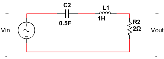
6. A RLC circuit is shown below. a. Determine its transfer function Vout/(Vin ) using the voltage divider method. b. Now using MATLAB, create a
6. A RLC circuit is shown below.

a. Determine its transfer function Vout/(Vin ) using the voltage divider method.
b. Now using MATLAB, create a Bode plot of the transfer function of the circuit and paste it below.
c. Determine what kind of filter (low pass, high pass, bandpass or band stop) the circuit is.
d. Using the methods explained in class, estimate the numerical value of the transfer function, as a complex number, at the following three frequencies: DC or 0 radians/sec; 1 radian/sec; and as frequency approaches infinity. Express the results in polar form of complex numbers.
e. Find the Step response of the circuit, using Matlab.
f. Using your result in 6.(e), discuss the stability of the system.
C2 1 1H R2 2 Vout 0.5FStep by Step Solution
There are 3 Steps involved in it
Step: 1

Get Instant Access to Expert-Tailored Solutions
See step-by-step solutions with expert insights and AI powered tools for academic success
Step: 2

Step: 3

Ace Your Homework with AI
Get the answers you need in no time with our AI-driven, step-by-step assistance
Get Started


