Question
6.10 Given the SR flip-flop of Fig. P6.10a, complete the timing diagram of Fig. P6.10b by determining the waveform of the output Q. Note

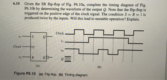
6.10 Given the SR flip-flop of Fig. P6.10a, complete the timing diagram of Fig. P6.10b by determining the waveform of the output Q. Note that the flip-flop is triggered on the positive edge of the clock signal. The condition S = R = 1 is produced twice by the inputs. Will this lead to unstable operation? Explain. S Clock PC P Clock X2 X2 R - e (a) Figure P6.10 (a) Flip-flop. (b) Timing diagram. (b)
Step by Step Solution
3.41 Rating (151 Votes )
There are 3 Steps involved in it
Step: 1
610 241 clock R Q clock 241 22 Positive edge clock The change in output appears o...
Get Instant Access to Expert-Tailored Solutions
See step-by-step solutions with expert insights and AI powered tools for academic success
Step: 2

Step: 3

Ace Your Homework with AI
Get the answers you need in no time with our AI-driven, step-by-step assistance
Get StartedRecommended Textbook for
Fundamentals of Digital Logic and Microcontrollers
Authors: M. Rafiquzzaman
6th edition
1-118-85579-9, 1118855795, 9781118969304, 978-1118855799
Students also viewed these Programming questions
Question
Answered: 1 week ago
Question
Answered: 1 week ago
Question
Answered: 1 week ago
Question
Answered: 1 week ago
Question
Answered: 1 week ago
Question
Answered: 1 week ago
Question
Answered: 1 week ago
Question
Answered: 1 week ago
Question
Answered: 1 week ago
Question
Answered: 1 week ago
Question
Answered: 1 week ago
Question
Answered: 1 week ago
Question
Answered: 1 week ago
Question
Answered: 1 week ago
Question
Answered: 1 week ago
Question
Answered: 1 week ago
Question
Answered: 1 week ago
Question
Answered: 1 week ago
Question
Answered: 1 week ago
Question
Answered: 1 week ago
Question
Answered: 1 week ago
View Answer in SolutionInn App


