Answered step by step
Verified Expert Solution
Question
1 Approved Answer
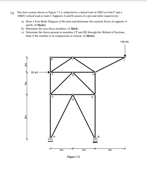
7.2 The truss system shown in Figure 7.2 is subjected to a lateral load of 20kN at Joint F and a 100kN vertical load

7.2 The truss system shown in Figure 7.2 is subjected to a lateral load of 20kN at Joint F and a 100kN vertical load at Joint J. Supports A and B consist of a pin and roller respectively: a) Draw a Free-Body Diagram of the truss and determine the reaction forces at supports A and B. (3 Marks) b) Determine the zero-force members. (1 Mark) c) Determine the forces present in members CF and HE through the Method of Sections. State if the member is in compression or tension. (3 Marks) 3m 20 kN D 3m Figure 7.2 3m H E D 4m 100 kN
Step by Step Solution
There are 3 Steps involved in it
Step: 1

Get Instant Access to Expert-Tailored Solutions
See step-by-step solutions with expert insights and AI powered tools for academic success
Step: 2

Step: 3

Ace Your Homework with AI
Get the answers you need in no time with our AI-driven, step-by-step assistance
Get Started


