Question
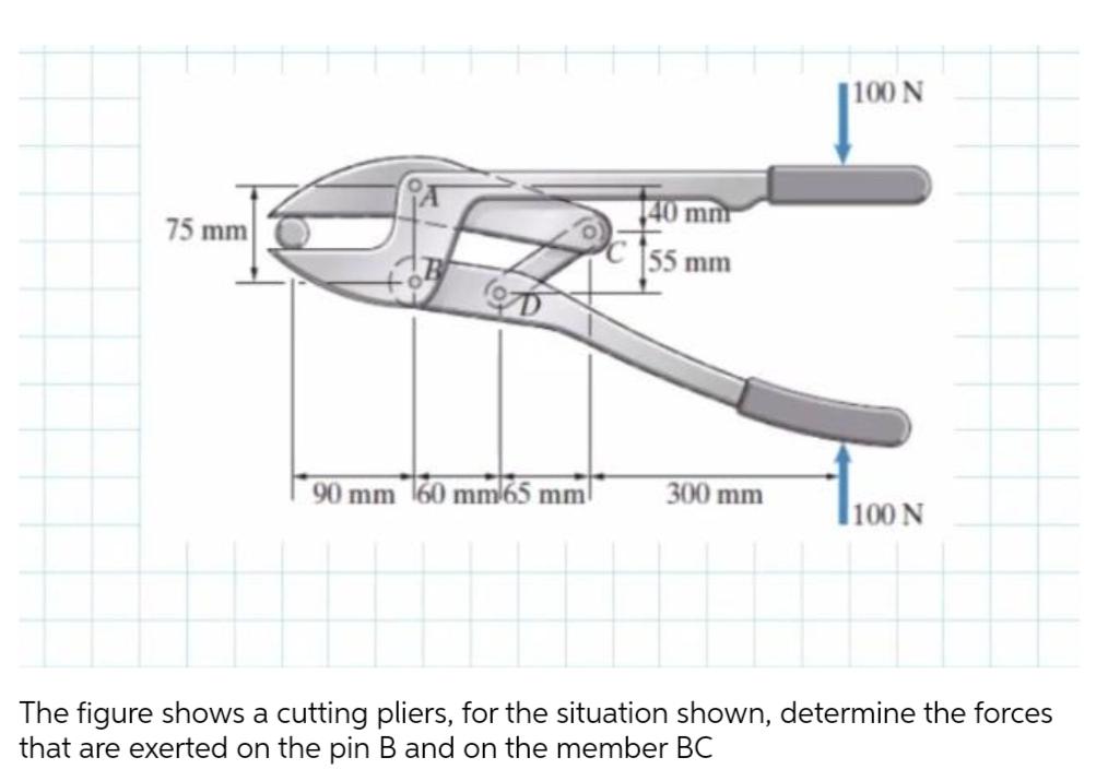
75 mm loD 90 mm 60 mm 65 mm mm 55 mm 300 mm 100 N 100 N The figure shows a cutting pliers,

75 mm loD 90 mm 60 mm 65 mm mm 55 mm 300 mm 100 N 100 N The figure shows a cutting pliers, for the situation shown, determine the forces that are exerted on the pin B and on the member BC
Step by Step Solution
3.44 Rating (160 Votes )
There are 3 Steps involved in it
Step: 1
The detailed ...
Get Instant Access to Expert-Tailored Solutions
See step-by-step solutions with expert insights and AI powered tools for academic success
Step: 2

Step: 3

Ace Your Homework with AI
Get the answers you need in no time with our AI-driven, step-by-step assistance
Get StartedRecommended Textbook for
Shigleys Mechanical Engineering Design
Authors: Richard G. Budynas, J. Keith Nisbett
9th edition
77679520, 73529281, 1259986241, 978-0077679521, 9780073529288, 9781259986246, 978-1121345317
Students also viewed these Mechanical Engineering questions
Question
Answered: 1 week ago
Question
Answered: 1 week ago
Question
Answered: 1 week ago
Question
Answered: 1 week ago
Question
Answered: 1 week ago
Question
Answered: 1 week ago
Question
Answered: 1 week ago
Question
Answered: 1 week ago
Question
Answered: 1 week ago
Question
Answered: 1 week ago
Question
Answered: 1 week ago
Question
Answered: 1 week ago
Question
Answered: 1 week ago
Question
Answered: 1 week ago
Question
Answered: 1 week ago
Question
Answered: 1 week ago
Question
Answered: 1 week ago
Question
Answered: 1 week ago
View Answer in SolutionInn App


