Answered step by step
Verified Expert Solution
Question
1 Approved Answer
9:14 1 Back LAB EVALUATION#3 1 of 3 C CONESTOGA STUDENT NAME: STUDENT NAME: 57 LAB EVALUATION #3 AUTOMATION I MACH8090 SEC2 LAB EVALUATION


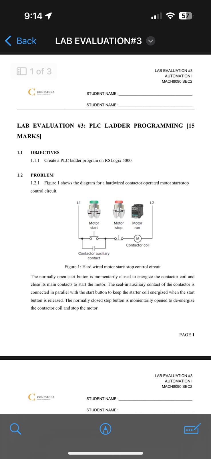
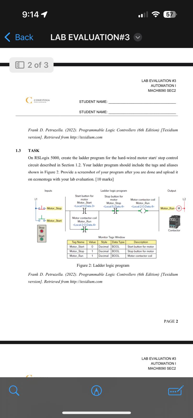
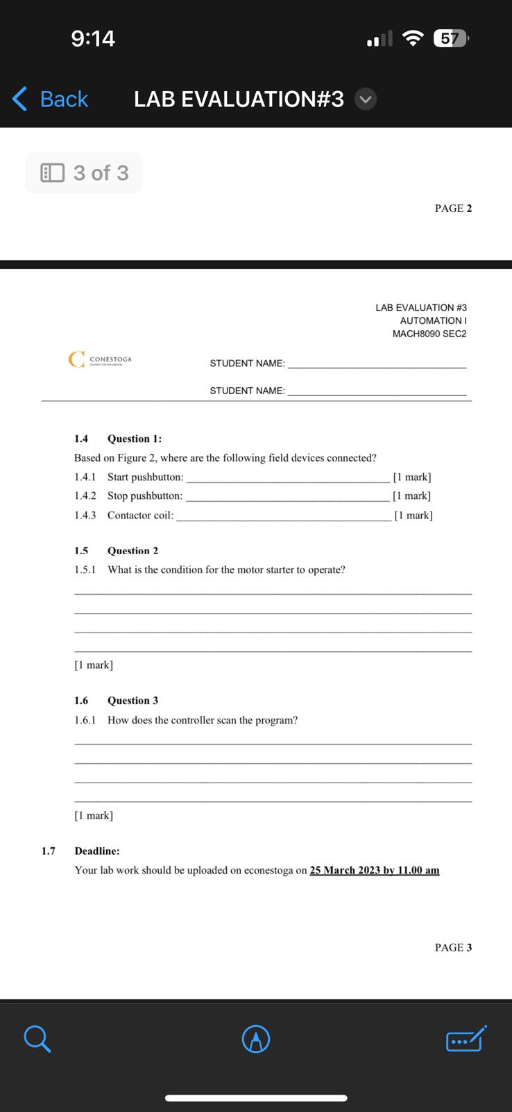
9:14 1 Back LAB EVALUATION#3 1 of 3 C CONESTOGA STUDENT NAME: STUDENT NAME: 57 LAB EVALUATION #3 AUTOMATION I MACH8090 SEC2 LAB EVALUATION #3: PLC LADDER PROGRAMMING [15 MARKS] 1.1 OBJECTIVES 1.1.1 Create a PLC ladder program on RSLogix 5000. 1.2 PROBLEM 1.2.1 Figure 1 shows the diagram for a hardwired contactor operated motor start/stop control circuit. Motor start Motor stop Motor run Contactor auxiliary contact Contactor coil L2 Figure 1: Hard wired motor start/stop control circuit The normally open start button is momentarily closed to energize the contactor coil and close its main contacts to start the motor. The seal-in auxiliary contact of the contactor is connected in parallel with the start button to keep the starter coil energized when the start button is released. The normally closed stop button is momentarily opened to de-energize the contactor coil and stop the motor. CONESTOGA STUDENT NAME: STUDENT NAME: PAGE 1 LAB EVALUATION #3 AUTOMATION I MACH8090 SEC2 E 9:14 1 Back LAB EVALUATION#3 2 of 3 C CONESTOGA STUDENT NAME: STUDENT NAME: : 57 LAB EVALUATION #3 AUTOMATION I MACH8090 SEC2 Frank D. Petruzella. (2022). Programmable Logic Controllers (6th Edition) [Texidium version]. Retrieved from http://texidium.com 1.3 TASK On RSLogix 5000, create the ladder program for the hard-wired motor start/stop control circuit described in Section 1.2. Your ladder program should include the tags and aliases shown in Figure 2. Provide a screenshot of your program after you are done and upload it on econestoga with your lab evaluation. [10 marks] Inputs L1 Motor Stop Start button for Ladder logic program Stop button for motor Motor Start motor Motor Stop Motor contactor coil Motor Run -Motor Start Motor contactor coil Motor_Run Stop Start Monitor Tags Window Tag Name Motor_Start Motor Stop Value 1 Style Data Type Decimal BOOL Decimal BOOL Description Start button for motor Stop button for motor Motor Run 1 Decimal BOOL Motor contactor coll Output L2 Motor Run-M Contactor Figure 2: Ladder logic program Frank D. Petruzella. (2022). Programmable Logic Controllers (6th Edition) [Texidium version]. Retrieved from http://texidium.com PAGE 2 LAB EVALUATION #3 AUTOMATION I MACH8090 SEC2 1.7 9:14 Back LAB EVALUATION#3 3 of 3 C CONESTOGA STUDENT NAME: STUDENT NAME: 1.4 Question 1: Based on Figure 2, where are the following field devices connected? 1.4.1 Start pushbutton: 1.4.2 Stop pushbutton: 1.4.3 Contactor coil: 1.5 Question 2 1.5.1 What is the condition for the motor starter to operate? [1 mark] 1.6 1.6.1 Question 3 How does the controller scan the program? [1 mark] : 57 PAGE 2 LAB EVALUATION #3 AUTOMATION I MACH8090 SEC2 [1 mark] [1 mark] [1 mark] Deadline: Your lab work should be uploaded on econestoga on 25 March 2023 by 11.00 am a A PAGE 3
Step by Step Solution
There are 3 Steps involved in it
Step: 1

Get Instant Access to Expert-Tailored Solutions
See step-by-step solutions with expert insights and AI powered tools for academic success
Step: 2

Step: 3

Ace Your Homework with AI
Get the answers you need in no time with our AI-driven, step-by-step assistance
Get Started


