Answered step by step
Verified Expert Solution
Question
1 Approved Answer
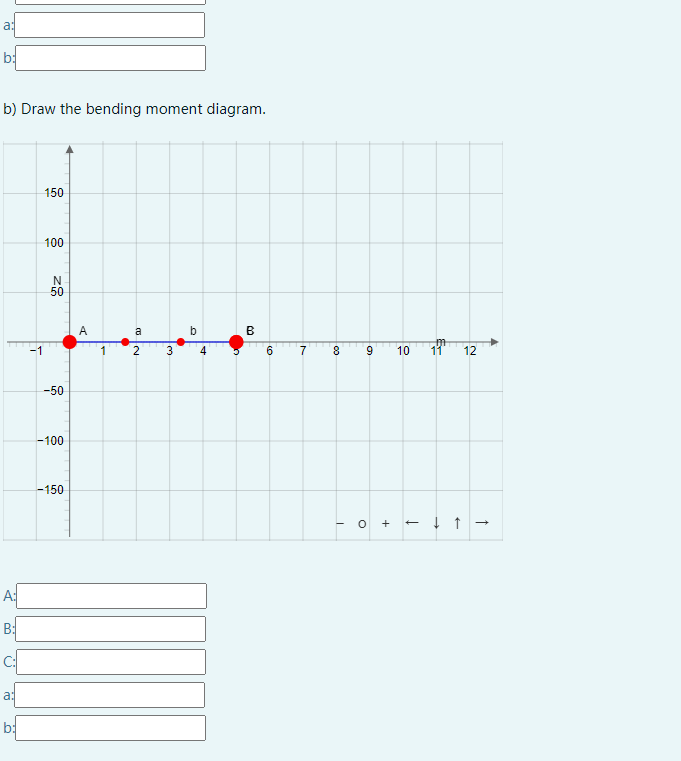
a: b: b) Draw the bending moment diagram. 150 100 gz N 50 -50 A a b B 1 2 3 4 6 7


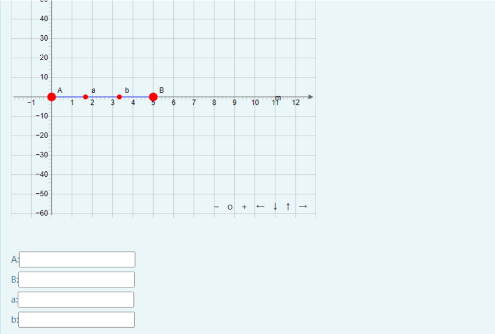
a: b: b) Draw the bending moment diagram. 150 100 gz N 50 -50 A a b B 1 2 3 4 6 7 8 -100 -150 A: B: a: b: 9 10 10 11 & + 12 - - Given a distributed load w = 13N/m is applied to the beam, that is support by a wall A. A clockwise-moment M = 7N-m is applied to point B. If a = 5m, draw the shear force and bending moment diagram. Assume upward force and counter-clockwise moment positive. Make sure all answer fields are answered. A a M To avoid losing marks, please note: 1. Make sure all answer fields are answered. 2. Note that the line should go from A to G in the positive x direction. The letters on the diagrams does not necessarily correspond to the labels in the question plot. If there are two points at the same location, the letter earlier in the alphabet is to the left of the concentrated load/couple moment, while the other one is to the right of it. 3. You can drag the points or input them in the blanks below, in the syntax [x,y). Each point corresponds to the ends of a line segment. Some points have the correct x-coordinate given and cannot be changed. 4. Points with lower case letters are used to control the shape of the curves (concave up or down), and therefore can be moved along the x axis. Their coordinates do not need to be precise. a) Draw the shear force diagram. 40 30 20 10 10 A a b B -1 1 2 3 4 6 7 8 -10 -201 -30 A: B: a: b: 6 E- 10 19 -40 -50 -60 + T 12 >
Step by Step Solution
There are 3 Steps involved in it
Step: 1

Get Instant Access to Expert-Tailored Solutions
See step-by-step solutions with expert insights and AI powered tools for academic success
Step: 2

Step: 3

Ace Your Homework with AI
Get the answers you need in no time with our AI-driven, step-by-step assistance
Get Started


