Question
a) Design a simple 4-bit ripple carry adder using 4 full adders in black box form Modify the 4-bit adder circuit you designed so that
a) Design a simple 4-bit ripple carry adder using 4 full adders in black box form
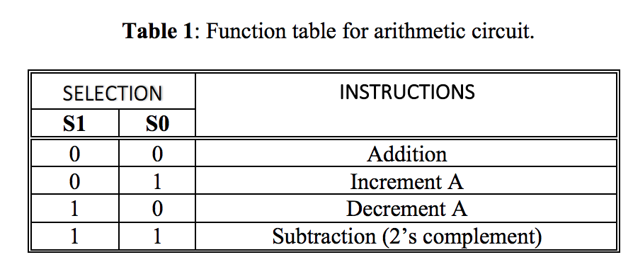
Modify the 4-bit adder circuit you designed so that it can now implement the arithmetic operations contained in Table 1. You must not change the selection-line encodings of instructions.

b) Start by determining F0 - the logic for controlling the carry into the first stage. Show all of your work including truth table and logic equation.
c) now determine F1 - the decoding logic for selecting the operations; that is, for input B. Show all of your work including truth table, logic equations, and K-map
d) create a single 1-bit slice, encapsulate it is a component, and then connect four 1-bit slices together to form a 4-bit arithmetic circuit.
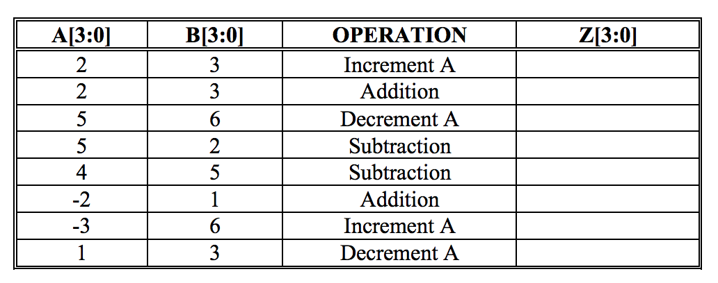
e) complete the table below.

Table 1: Function table for arithmetic circuit. INSTRUCTIONS SELECTION si so 0 0 Addition 0 Increment A Decrement A Subtraction (2s complement) A[3:0) OPERATION Z[3:0) 3 3 Increment A Addition Decrement A Subtraction Subtraction Addition Increment A Decrement A 5 1 6 3 Table 1: Function table for arithmetic circuit. INSTRUCTIONS SELECTION si so 0 0 Addition 0 Increment A Decrement A Subtraction (2s complement) A[3:0) OPERATION Z[3:0) 3 3 Increment A Addition Decrement A Subtraction Subtraction Addition Increment A Decrement A 5 1 6 3
Step by Step Solution
There are 3 Steps involved in it
Step: 1

Get Instant Access to Expert-Tailored Solutions
See step-by-step solutions with expert insights and AI powered tools for academic success
Step: 2

Step: 3

Ace Your Homework with AI
Get the answers you need in no time with our AI-driven, step-by-step assistance
Get Started


