Question: a) Enter the plant transfer function () into Matlab at the command window and load sisotool. b) If you want, to minimise distraction, temporarily hide

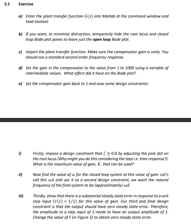
a) Enter the plant transfer function () into Matlab at the command window and load sisotool. b) If you want, to minimise distraction, temporarily hide the root locus and closed loop Bode plot panes to leave just the open loop Bode plot. c) Import the plant transfer function. Make sure the compensator gain is unity. You should see a standard second order frequency response. d) Set the gain in the compensator to the value from 1 to 1000 using a variable of intermediate values. What effect did it have on the Bode plot? e) Set the compensator gain back to 1 and now some design constraints: i) Firstly, impose a design constraint that 0.8 by adjusting the pink dot on the root locus(Why might you do this considering the step i.e. time response?). What is the maximum value of gain, , that can be used? ii) Now find the value of for the closed loop system at this value of gain. Lets call this and use it as a second design constraint; we want the natural frequency of the final system to be (approximately) . iii) Thirdly, show that there is a substantial steady state error in response to a unit step input (() = 1) for this value of gain. Our third and final design constraint is that the output should have zero steady state error. Therefore, the amplitude to a step input of 1 needs to have an output amplitude of 1. Change the value of F (in Figure 2) to obtain zero steady state error.
5.1 Exercise a) Enter the plant transfer function (s) into Matlab at the command window and load sisotool. b) if you want, to minimise distraction, temporarily hide the root locus and closed loop Bode plot panes to leave just the open loop Bode plot. c) Import the plant transfer function. Make sure the compensator gain is unity. You should see a standard second order frequency response. d) Set the gain in the compensator to the value from 1 to 1000 using a variable of intermediate values. What effect did it have on the Bode plot? e) Set the compensator gain back to 1 and now some design constraints: i) Firstly, impose a design constraint that > > 0.8 by adjusting the pink dot on the root locus (Why might you do this considering the step i.e. time response?). What is the maximum value of gain, K, that can be used? ii) Now find the value of w for the closed loop system at this value of gain. Let's call this wd and use it as a second design constraint; we want the natural frequency of the final system to be (approximately) wd. iii) Thirdly, show that there is a substantial steady state error in response to a unit step input (r(s) = 1/s) for this value of gain. Our third and final design constraint is that the output should have zero steady state error. Therefore, the amplitude to a step input of 1 needs to have an output amplitude of 1. Change the value of F (in Figure 2) to obtain zero steady state error
Step by Step Solution
There are 3 Steps involved in it

Get step-by-step solutions from verified subject matter experts


