Question
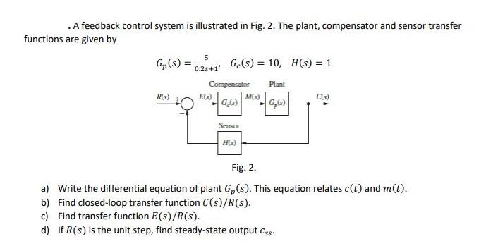
. A feedback control system is illustrated in Fig. 2. The plant, compensator and sensor transfer functions are given by Gp(s) = R(s) 5

. A feedback control system is illustrated in Fig. 2. The plant, compensator and sensor transfer functions are given by Gp(s) = R(s) 5 0.2s+1' Ge(s)= 10, H(s) = 1 Compensator G_(s) E(s) Sensor HG) MG) Plant G(s) C(s) Fig. 2. a) Write the differential equation of plant Gp(s). This equation relates c(t) and m(t). b) Find closed-loop transfer function C(s)/R(s). c) Find transfer function E(s)/R(s). d) If R (s) is the unit step, find steady-state output Css.
Step by Step Solution
There are 3 Steps involved in it
Step: 1
SOLUTION a To write the differential equation of the plant Gs we can consider the transfer function ...
Get Instant Access to Expert-Tailored Solutions
See step-by-step solutions with expert insights and AI powered tools for academic success
Step: 2

Step: 3

Ace Your Homework with AI
Get the answers you need in no time with our AI-driven, step-by-step assistance
Get StartedRecommended Textbook for
Control Systems Engineering
Authors: Norman S. Nise
7th Edition
1118170512, 978-1118170519
Students also viewed these Business Communication questions
Question
Answered: 1 week ago
Question
Answered: 1 week ago
Question
Answered: 1 week ago
Question
Answered: 1 week ago
Question
Answered: 1 week ago
Question
Answered: 1 week ago
Question
Answered: 1 week ago
Question
Answered: 1 week ago
Question
Answered: 1 week ago
Question
Answered: 1 week ago
Question
Answered: 1 week ago
Question
Answered: 1 week ago
Question
Answered: 1 week ago
Question
Answered: 1 week ago
Question
Answered: 1 week ago
Question
Answered: 1 week ago
Question
Answered: 1 week ago
Question
Answered: 1 week ago
Question
Answered: 1 week ago
Question
Answered: 1 week ago
Question
Answered: 1 week ago
Question
Answered: 1 week ago
View Answer in SolutionInn App


