Answered step by step
Verified Expert Solution
Question
1 Approved Answer
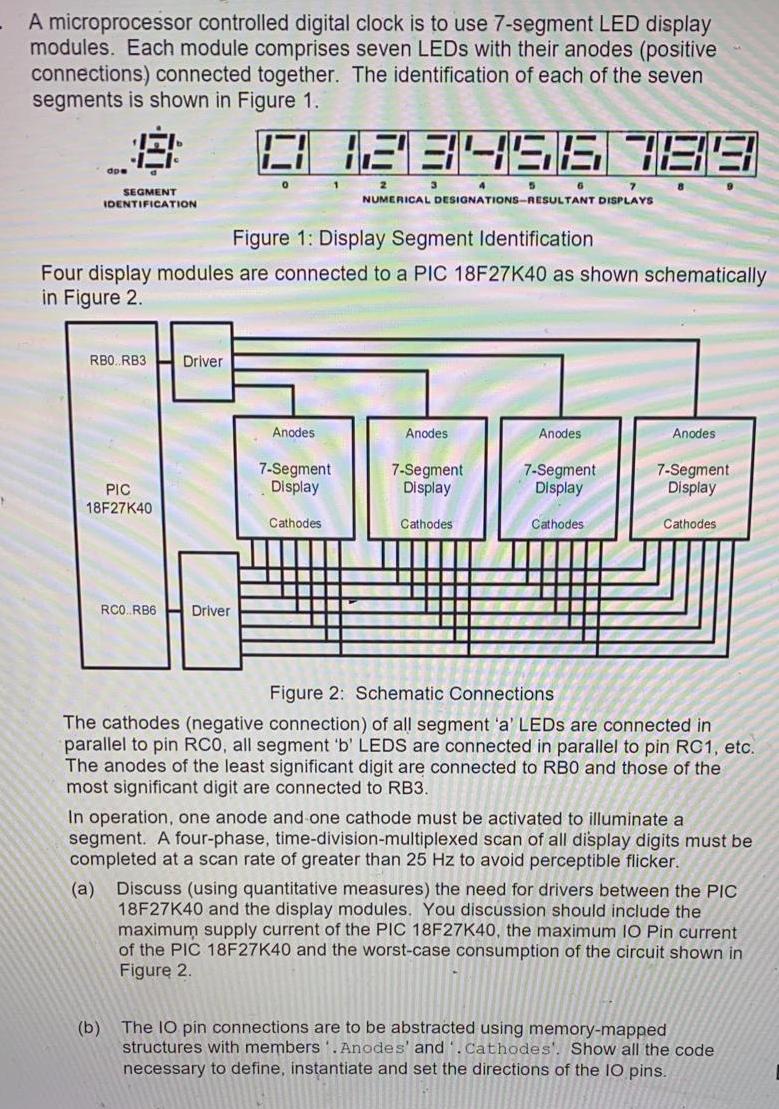
A microprocessor controlled digital clock is to use 7-segment LED display modules. Each module comprises seven LEDs with their anodes (positive connections) connected together.


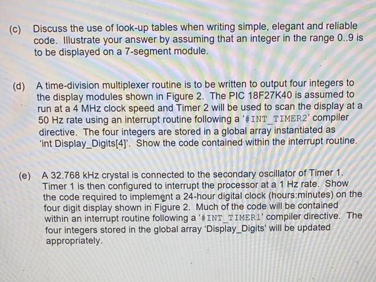
A microprocessor controlled digital clock is to use 7-segment LED display modules. Each module comprises seven LEDs with their anodes (positive connections) connected together. The identification of each of the seven segments is shown in Figure 1. 18 SEGMENT IDENTIFICATION . RBO RB3 PIC 18F27K40 RCO. RB6 Driver (b) 0123456 789 3 8 Driver 0 Figure 1: Display Segment Identification Four display modules are connected to a PIC 18F27K40 as shown schematically in Figure 2. Anodes 1 7-Segment Display Cathodes 2 7 NUMERICAL DESIGNATIONS-RESULTANT DISPLAYS 4 Anodes 7-Segment Display Cathodes 5 6 Anodes 7-Segment Display Cathodes Anodes 9 7-Segment Display Cathodes Figure 2: Schematic Connections The cathodes (negative connection) of all segment 'a' LEDs are connected in parallel to pin RCO, all segment 'b' LEDS are connected in parallel to pin RC1, etc. The anodes of the least significant digit are connected to RBO and those of the most significant digit are connected to RB3. In operation, one anode and one cathode must be activated to illuminate a segment. A four-phase, time-division-multiplexed scan of all display digits must be completed at a scan rate of greater than 25 Hz to avoid perceptible flicker. (a) Discuss (using quantitative measures) the need for drivers between the PIC 18F27K40 and the display modules. You discussion should include the maximum supply current of the PIC 18F27K40, the maximum IO Pin current of the PIC 18F27K40 and the worst-case consumption of the circuit shown in Figure 2. The 10 pin connections are to be abstracted using memory-mapped structures with members. Anodes' and '. Cathodes'. Show all the code necessary to define, instantiate and set the directions of the IO pins. (c) Discuss the use of look-up tables when writing simple, elegant and reliable code. Illustrate your answer by assuming that an integer in the range 0..9 is to be displayed on a 7-segment module. (d) A time-division multiplexer routine is to be written to output four integers to the display modules shown in Figure 2. The PIC 18F27K40 is assumed to run at a 4 MHz clock speed and Timer 2 will be used to scan the display at a 50 Hz rate using an interrupt routine following a '#INT TIMER2' compiler directive. The four integers are stored in a global array instantiated as 'int Display_Digits[4]'. Show the code contained within the interrupt routine. (e) A 32.768 kHz crystal is connected to the secondary oscillator of Timer 1. Timer 1 is then configured to interrupt the processor at a 1 Hz rate. Show the code required to implement a 24-hour digital clock (hours:minutes) on the four digit display shown in Figure 2. Much of the code will be contained within an interrupt routine following a '#INT_TIMER1' compiler directive. The four integers stored in the global array 'Display_Digits' will be updated appropriately.
Step by Step Solution
★★★★★
3.49 Rating (156 Votes )
There are 3 Steps involved in it
Step: 1
AnswerA In digital equipment a display driver is typically a semiconductor coordinated circ...
Get Instant Access to Expert-Tailored Solutions
See step-by-step solutions with expert insights and AI powered tools for academic success
Step: 2

Step: 3

Ace Your Homework with AI
Get the answers you need in no time with our AI-driven, step-by-step assistance
Get Started


