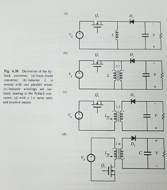
A nonideal flyback converter. The flyback converter shown in Fig. 6.30(d) operates in the continuous conduction mode. The MOSFET has on-resistance R, and the


A nonideal flyback converter. The flyback converter shown in Fig. 6.30(d) operates in the continuous conduction mode. The MOSFET has on-resistance R, and the diode has a constant forward voltage drop Vp. The flyback transformer has primary winding resistance R, and secondary winding resistance R. Derive a complete steady-state equivalent circuit model, which is valid in the continuous con- (a) duction mode, and which correctly models the loss elements listed above as well as the converter input and output ports. Sketch your equivalent circuit. Derive an analytical expression for the converter efficiency. (b) (a) D, V, L. (b) D, T:1 Fig. 6.30 back converter: (a) buck-boost converter; (b) inductor L is wound with two parallel wires; (c) inductor windings are iso- lated, leading to the flyback con- verter; (d) with a In turns ratio and positive output. Derivation of the fly- (c) D, 1:1 LM. (d) 1:n D, LM. ieee ele eee ele ST
Step by Step Solution
3.42 Rating (161 Votes )
There are 3 Steps involved in it
Step: 1

See step-by-step solutions with expert insights and AI powered tools for academic success
Step: 2

Step: 3

Ace Your Homework with AI
Get the answers you need in no time with our AI-driven, step-by-step assistance
Get Started


