Question
A student constructed a simple DIY robotic arm with two degrees of freedom to help him understands the kinematics of robotic arm. As shown

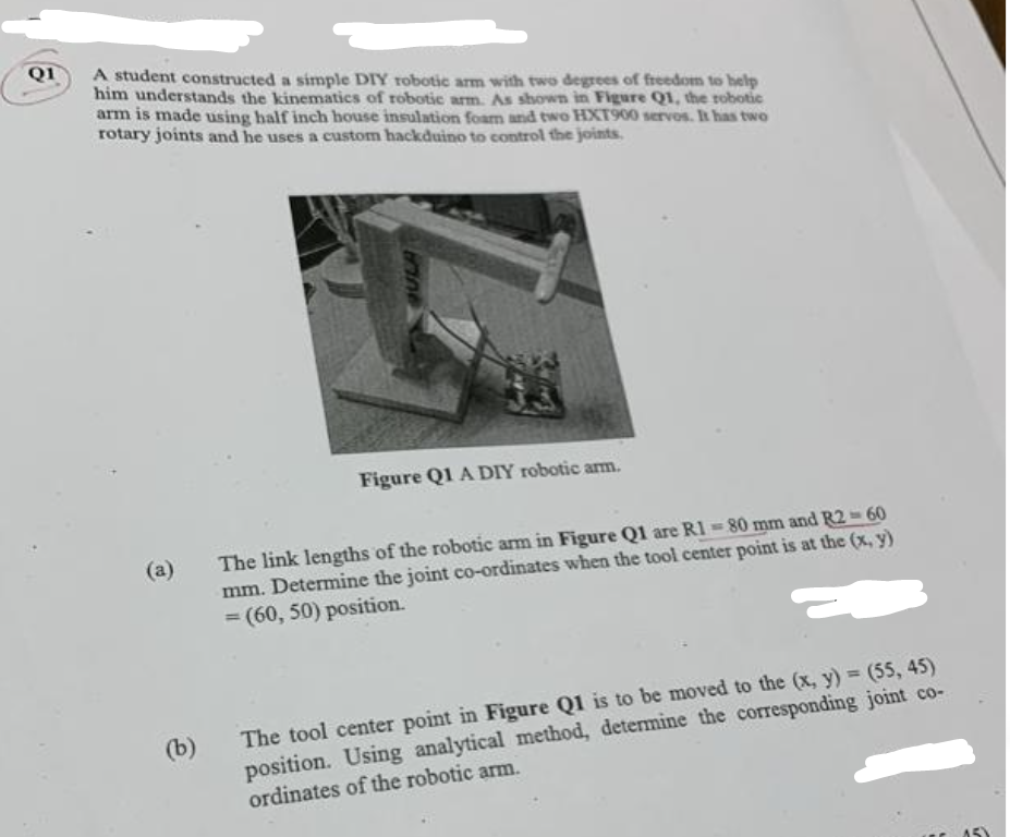
A student constructed a simple DIY robotic arm with two degrees of freedom to help him understands the kinematics of robotic arm. As shown in Figure Q1, the robotic arm is made using half inch house insulation foam and two HXT900 servos. It has two rotary joints and he uses a custom hackduino to control the joints. (a) (b) Figure Q1 A DIY robotic arm. The link lengths of the robotic arm in Figure Q1 are R1-80 mm and R2-60 mm. Determine the joint co-ordinates when the tool center point is at the (x, y) = (60, 50) position. The tool center point in Figure Q1 is to be moved to the (x, y) = (55, 45) position. Using analytical method, determine the corresponding joint co- ordinates of the robotic arm. 15)
Step by Step Solution
3.52 Rating (155 Votes )
There are 3 Steps involved in it
Step: 1

Get Instant Access to Expert-Tailored Solutions
See step-by-step solutions with expert insights and AI powered tools for academic success
Step: 2

Step: 3

Ace Your Homework with AI
Get the answers you need in no time with our AI-driven, step-by-step assistance
Get StartedRecommended Textbook for
Modern Control Systems
Authors: Richard C. Dorf, Robert H. Bishop
12th edition
136024580, 978-0136024583
Students also viewed these Mechanical Engineering questions
Question
Answered: 1 week ago
Question
Answered: 1 week ago
Question
Answered: 1 week ago
Question
Answered: 1 week ago
Question
Answered: 1 week ago
Question
Answered: 1 week ago
Question
Answered: 1 week ago
Question
Answered: 1 week ago
Question
Answered: 1 week ago
Question
Answered: 1 week ago
Question
Answered: 1 week ago
Question
Answered: 1 week ago
Question
Answered: 1 week ago
Question
Answered: 1 week ago
Question
Answered: 1 week ago
Question
Answered: 1 week ago
Question
Answered: 1 week ago
Question
Answered: 1 week ago
Question
Answered: 1 week ago
Question
Answered: 1 week ago
Question
Answered: 1 week ago
Question
Answered: 1 week ago
View Answer in SolutionInn App


