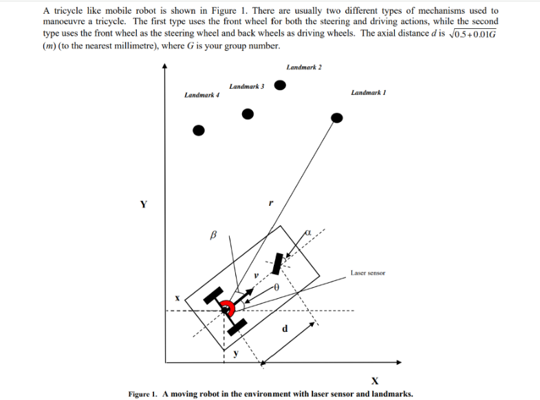
Question: A tricycle like mobile robot is shown in Figure 1. There are usually two different types of mechanisms used to manoeuvre a tricycle. The


A tricycle like mobile robot is shown in Figure 1. There are usually two different types of mechanisms used to manoeuvre a tricycle. The first type uses the front wheel for both the steering and driving actions, while the second type uses the front wheel as the steering wheel and back wheels as driving wheels. The axial distance d is 0.5 +0.01G (m) (to the nearest millimetre), where G is your group number. Landmark 4 Landmark 3 Landmark 2 d Landmark 1 Laser sensor X Figure 1. A moving robot in the environment with laser sensor and landmarks. Part I: Build and simulate the kinematic model of this robot 1. Derive kinematic equations for both types of mobile robots. 2. Using SIMULINK (a MATLAB toolbox) to build the kinematic models of the robots and simulate and demonstrate the behaviour of the vehicle subject to: i. Constant driving velocity and a constant steering angle. ii. Constant driving velocity and a linearly changing steering angle. iii. Linearly changing driving velocity and linearly changing steering angle. It is assumed that the maximum driving velocity is (1.5+0.03G) m/s, the maximum driving acceleration is (0.8+0.01G) m/s, the maximum steering angle and steering velocity are 1/4 rad, and 0.3 rad/s, respectively. (where G is your group number) 3. The robots are required to follow a trajectory shown in Figure 2. Plan the driving acceleration and steering velocity profiles for the front wheel steering and back wheel driving robot so that the robot will follow the path. Apply the same control profile to the front wheel steering and front wheel driving robot. Is the outcome the same? Why? A tricycle like mobile robot is shown in Figure 1. There are usually two different types of mechanisms used to manoeuvre a tricycle. The first type uses the front wheel for both the steering and driving actions, while the second type uses the front wheel as the steering wheel and back wheels as driving wheels. The axial distance d is 0.5+0.01G (m) (to the nearest millimetre), where G is your group number. Landmark 4 Landmark 3 Landmark 2 d Landmark 1 Laser sensor X Figure 1. A moving robot in the environment with laser sensor and landmarks. Part I: Build and simulate the kinematic model of this robot 1. Derive kinematic equations for both types of mobile robots. 2. Using SIMULINK (a MATLAB toolbox) to build the kinematic models of the robots and simulate and demonstrate the behaviour of the vehicle subject to: i. Constant driving velocity and a constant steering angle. ii. Constant driving velocity and a linearly changing steering angle. iii. Linearly changing driving velocity and linearly changing steering angle. It is assumed that the maximum driving velocity is (1.5+0.03G) m/s, the maximum driving acceleration is (0.8+0.01G) m/s, the maximum steering angle and steering velocity are 1/4 rad, and 0.3 rad/s, respectively. (where G is your group number) 3. The robots are required to follow a trajectory shown in Figure 2. Plan the driving acceleration and steering velocity profiles for the front wheel steering and back wheel driving robot so that the robot will follow the path. Apply the same control profile to the front wheel steering and front wheel driving robot. Is the outcome the same? Why?
Step by Step Solution
3.29 Rating (164 Votes )
There are 3 Steps involved in it

Get step-by-step solutions from verified subject matter experts


