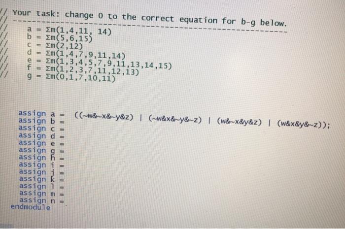
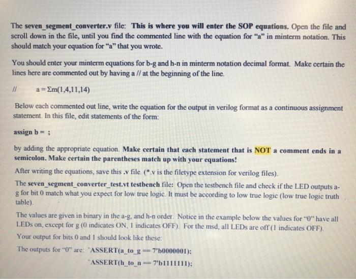
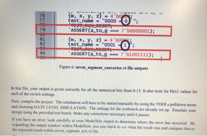
a = // Your task: change o to the correct equation for b-9 below. Em(1,4,11, 14) b Em(5,6,15) m (2,12) d = m(1,4,7,9,11,14) e = Em(1,3,4,5,7,9,11,13,14,15) f Em (1,2,3,7,11,12,13) 9 = Em(0,1,7,10,11) C ((~W&-&ny&z) | (~w&x&my&~2) (w&x&y&z) | (w&x&y&m-z)); assign a = assign b assign - assign d - assign e- assigng assign h assign i assignj assign k assign 1 assignm assign n endmodule The seven_segment_converter.v file: This is where you will enter the SOP equations. Open the file and scroll down in the file, until you find the commented line with the equation for "a" in minterm notation. This should match your equation for "a" that you wrote. You should enter your minterm equations for b-g and h-n in minterm notation decimal format. Make certain the lines here are commented out by having a // at the beginning of the line // a=Sm(1,4,11,14) Below each commented out line, write the equation for the output in verilog format as a continuous assignment statement. In this file, edit statements of the form: assign b=; by adding the appropriate equation. Make certain that each statement that is NOT a comment ends in a semicolon. Make certain the parentheses match up with your equations! After writing the equations, save this . file ("v is the filetype extension for verilog files). The seven_segment_converter_test.vt testbench file: Open the testbench file and check if the LED outputs a- g for bit O match what you expect for low true logic. It must be according to low true logic (low true logic truth table) The values are given in binary in the a-g, and h-n order. Notice in the example below the values for "O" have all LEDs on, except for g (0 indicates ON, 1 indicates OFF). For the msd, all LEDs are off (1 indicates OFF). Your output for bits 0 and 1 should look like these The outputs for "0" are: "ASSERT(a_to_g = 7'50000001): *ASSERT(h_to_n7"b1111111); ARE. 76 77 70 79 {w, x, y, z}'-"4'bo test_name - "00000"; TOT RUN-REST, ASSERT(a_to_g 7'b0000001); {w, x, y, z} 4'boga; test_name = "0001 TOTURBOLT ASSERT(a_to_g --- 7'b1001111); 81 82 09 84 Figure 6: seven_segment_converter.vt file outputs In this file, your output is given correctly for all the numerical bits from 0-15. It also tests for Hexl values for each of the switch settings. Now, compile the project. The simulation will have to be started manually by using the TOOLs pulldown menu and choosing GATE LEVEL SIMULATION; The settings for the testbench are already set up. Simulate your design using the provided test bench Make any corrections necessary until it passes. If you have an error, look carefully at your ModelSim output to determine where the error has occurred By expanding the output window within ModelSim, you can check to see what the result was and compare this to the expected result within seven_segment_test. vt file. a = // Your task: change o to the correct equation for b-9 below. Em(1,4,11, 14) b Em(5,6,15) m (2,12) d = m(1,4,7,9,11,14) e = Em(1,3,4,5,7,9,11,13,14,15) f Em (1,2,3,7,11,12,13) 9 = Em(0,1,7,10,11) C ((~W&-&ny&z) | (~w&x&my&~2) (w&x&y&z) | (w&x&y&m-z)); assign a = assign b assign - assign d - assign e- assigng assign h assign i assignj assign k assign 1 assignm assign n endmodule The seven_segment_converter.v file: This is where you will enter the SOP equations. Open the file and scroll down in the file, until you find the commented line with the equation for "a" in minterm notation. This should match your equation for "a" that you wrote. You should enter your minterm equations for b-g and h-n in minterm notation decimal format. Make certain the lines here are commented out by having a // at the beginning of the line // a=Sm(1,4,11,14) Below each commented out line, write the equation for the output in verilog format as a continuous assignment statement. In this file, edit statements of the form: assign b=; by adding the appropriate equation. Make certain that each statement that is NOT a comment ends in a semicolon. Make certain the parentheses match up with your equations! After writing the equations, save this . file ("v is the filetype extension for verilog files). The seven_segment_converter_test.vt testbench file: Open the testbench file and check if the LED outputs a- g for bit O match what you expect for low true logic. It must be according to low true logic (low true logic truth table) The values are given in binary in the a-g, and h-n order. Notice in the example below the values for "O" have all LEDs on, except for g (0 indicates ON, 1 indicates OFF). For the msd, all LEDs are off (1 indicates OFF). Your output for bits 0 and 1 should look like these The outputs for "0" are: "ASSERT(a_to_g = 7'50000001): *ASSERT(h_to_n7"b1111111); ARE. 76 77 70 79 {w, x, y, z}'-"4'bo test_name - "00000"; TOT RUN-REST, ASSERT(a_to_g 7'b0000001); {w, x, y, z} 4'boga; test_name = "0001 TOTURBOLT ASSERT(a_to_g --- 7'b1001111); 81 82 09 84 Figure 6: seven_segment_converter.vt file outputs In this file, your output is given correctly for all the numerical bits from 0-15. It also tests for Hexl values for each of the switch settings. Now, compile the project. The simulation will have to be started manually by using the TOOLs pulldown menu and choosing GATE LEVEL SIMULATION; The settings for the testbench are already set up. Simulate your design using the provided test bench Make any corrections necessary until it passes. If you have an error, look carefully at your ModelSim output to determine where the error has occurred By expanding the output window within ModelSim, you can check to see what the result was and compare this to the expected result within seven_segment_test. vt file


