Answered step by step
Verified Expert Solution
Question
1 Approved Answer
1.0 Objective 1. To construct a schematic diagram on a breadboard. 2. To correctly connect a voltmeter to a circuit. 3. To correctly connect


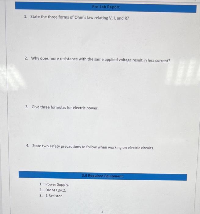
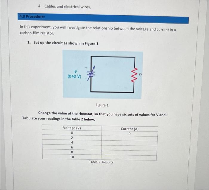
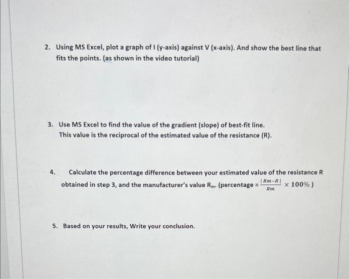
1.0 Objective 1. To construct a schematic diagram on a breadboard. 2. To correctly connect a voltmeter to a circuit. 3. To correctly connect an ammeter in a circuit. 4. Become familiar with electrical resistance and electrical resistors. 5. To verify the relation between the voltage and current through a resistor circuit. Ohm's Law: 2.0 Introduction Ohm's Law is the basis of many electrical circuit calculations which indicates V=I*R. In this experiment Ohms Law has to be verified and will prove that the current through a resistor is proportional to the voltage across it. The way in which we accomplish this is to measure the voltage across and the current through a known resistor for several different pairs of values. Data can then be plotted on a graph, and if the relationship is truly linear, it should yield a straight line. Resistor The ohm is the unit of resistance, and it is represented by the symbol 2 (Greek letter Omega). Resistance values are indicated by a standard color code that manufacturers have adopted. This code uses color band on the body of resistor. The colors and their numerical values are given in the resistor color chart, Table 1. This code is used for 1/8-w, 1/4-w, 1/2-w, 2-w, and 3- w resistors. (W stands for watt, i.e.is the power dissipation ability of the resistance). Website link: Resistor Color Code Calculator - 4 band, 5 band, 6 band | DigiKey Electronics Lead ))) first significant bit second significant bit Figure 4: 4-band resistance tolerance no. Of zeros Pre-Lab Report 1. State the three forms of Ohm's law relating V, I, and R? 2. Why does more resistance with the same applied voltage result in less current? 3. Give three formulas for electric power. 4. State two safety precautions to follow when working on electric circuits. 1. Power Supply. 2. DMM Qty:2. 3. 1 Resistor 3.0 Required Equipment: 3 4. Cables and electrical wires. 4.0 Procedure: In this experiment, you will investigate the relationship between the voltage and current in a carbon-film resistor. 1. Set up the circuit as shown in Figure 1. (042 V) Figure 1 Change the value of the rheostat, so that you have six sets of values for V and I. Tabulate your readings in the table 2 below. Voltage (V) 0 2 4 6 8 10 Table 2: Results Current (A) 0 2. Using MS Excel, plot a graph of I (y-axis) against V (x-axis). And show the best line that fits the points. (as shown in the video tutorial) 3. Use MS Excel to find the value of the gradient (slope) of best-fit line. This value is the reciprocal of the estimated value of the resistance (R). 4. Calculate the percentage difference between your estimated value of the resistance R obtained in step 3, and the manufacturer's value Rm. (percentage =- x 100% ) | Rm-R| Rm 5. Based on your results, Write your conclusion.
Step by Step Solution
★★★★★
3.41 Rating (173 Votes )
There are 3 Steps involved in it
Step: 1
1 State the three form of ohms law relating VIR Ans Ohms Law The potential difference ...
Get Instant Access to Expert-Tailored Solutions
See step-by-step solutions with expert insights and AI powered tools for academic success
Step: 2

Step: 3

Ace Your Homework with AI
Get the answers you need in no time with our AI-driven, step-by-step assistance
Get Started


