Question
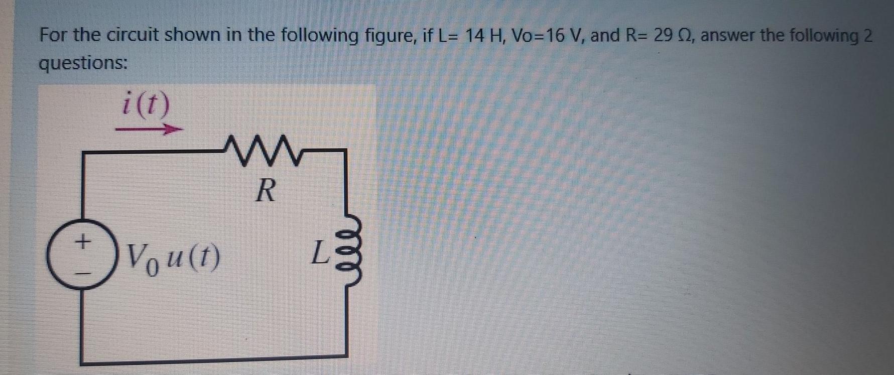
For the circuit shown in the following figure, if L= 14 H, Vo=16 V, and R= 29 Q, answer the following 2 questions: i(1)


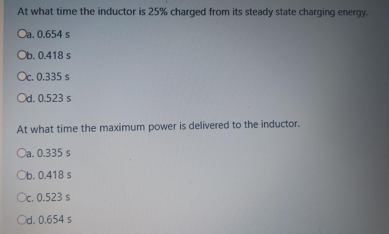
For the circuit shown in the following figure, if L= 14 H, Vo=16 V, and R= 29 Q, answer the following 2 questions: i(1) R ell At what time the inductor is 25% charged from its steady state charging energy. Oa. 0.654 s Ob. 0.418 s Oc. 0.335 s Od. 0.523 s At what time the maximum power is delivered to the inductor. Oa. 0.335 s Ob. 0.418 s Oc. 0.523 s Od. 0.654 s
Step by Step Solution
3.44 Rating (151 Votes )
There are 3 Steps involved in it
Step: 1

Get Instant Access to Expert-Tailored Solutions
See step-by-step solutions with expert insights and AI powered tools for academic success
Step: 2

Step: 3

Ace Your Homework with AI
Get the answers you need in no time with our AI-driven, step-by-step assistance
Get StartedRecommended Textbook for
System Dynamics
Authors: William Palm III
3rd edition
73398063, 978-0073398068
Students also viewed these Electrical Engineering questions
Question
Answered: 1 week ago
Question
Answered: 1 week ago
Question
Answered: 1 week ago
Question
Answered: 1 week ago
Question
Answered: 1 week ago
Question
Answered: 1 week ago
Question
Answered: 1 week ago
Question
Answered: 1 week ago
Question
Answered: 1 week ago
Question
Answered: 1 week ago
Question
Answered: 1 week ago
Question
Answered: 1 week ago
Question
Answered: 1 week ago
Question
Answered: 1 week ago
Question
Answered: 1 week ago
Question
Answered: 1 week ago
Question
Answered: 1 week ago
Question
Answered: 1 week ago
Question
Answered: 1 week ago
Question
Answered: 1 week ago
View Answer in SolutionInn App


