Answered step by step
Verified Expert Solution
Question
1 Approved Answer
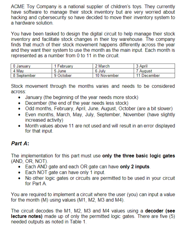
ACME Toy Company is a national supplier of children's toys. They currently have software to manage their stock inventory but are very worried about hacking
ACME Toy Company is a national supplier of children's toys. They currently
have software to manage their stock inventory but are very worried about
hacking and cybersecurity so have decided to move their inventory system to
a hardware solution.
You have been tasked to design the digital circuit to help manage their stock
inventory and facilitate stock changes in their toy warehouse. The company
finds that much of their stock movement happens differently across the year
and they want their system to use the month as the main input. Each month is
represented as a number from to in the circuit.
Stock movement through the months varies and needs to be considered
across:
January the beginning of the year needs more stock
December the end of the year needs less stock
Odd months, February, April, June, August, October are a bit slower
Even months, March, May, July, September, November have slightly
increased activity
Month values above are not used and will result in an error displayed
for that input.
Part A:
The implementation for this part must use only the three basic logic gates
AND OR NOT
Each AND gate and each OR gate can have only inputs.
Each NOT gate can have only input.
No other logic gates or circuits are permitted to be used in your circuit
for Part A
You are required to implement a circuit where the user you can input a value
for the month M using values M M M and M
The circuit decodes the M M M and M values using a decoder see
lecture notes made up of only the permitted logic gates. There are five
needed outputs as noted in Table Table : Input and output values for Part A
tableINPUTOUTPUTMMMMJanuary,tableEvenmonthtableOddmonthDecember,Error,
For Part A each of the five outputs will be displayed with a single output pin green circle in Logisim resulting in outputs for your Part A circuit:
make a logism circuit for the following

Step by Step Solution
There are 3 Steps involved in it
Step: 1

Get Instant Access to Expert-Tailored Solutions
See step-by-step solutions with expert insights and AI powered tools for academic success
Step: 2

Step: 3

Ace Your Homework with AI
Get the answers you need in no time with our AI-driven, step-by-step assistance
Get Started


