Answered step by step
Verified Expert Solution
Question
1 Approved Answer
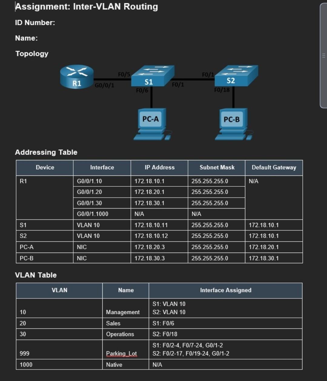
Addressing Table VLAN Table Step 2: Manually configure S1's trunk interface F0/5 a. Configure S1 's interface F0/5 with the same trunk parameters as F0/1.


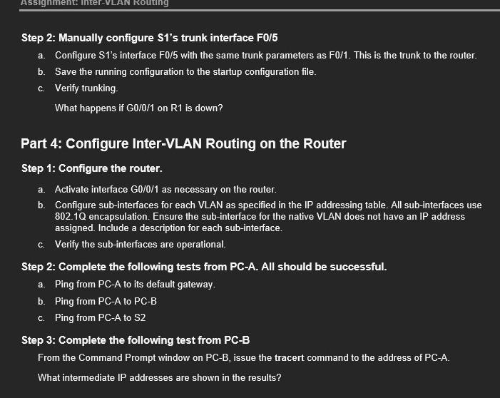
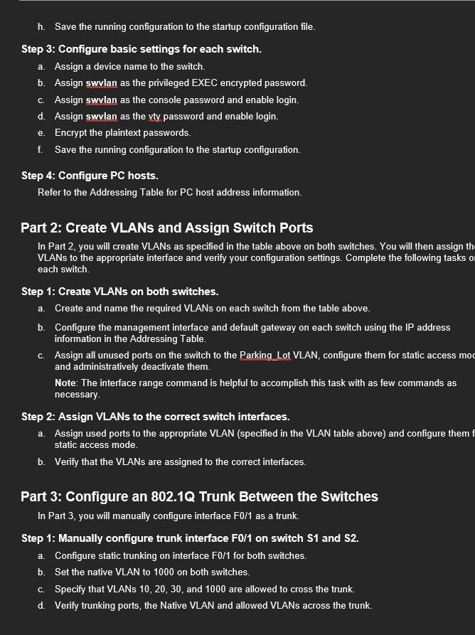
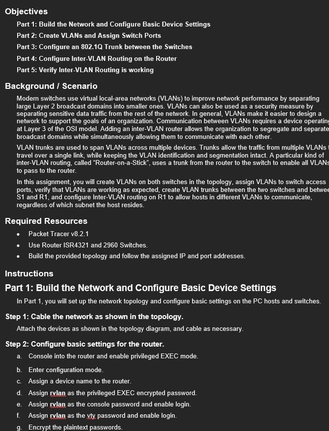
Addressing Table VLAN Table Step 2: Manually configure S1's trunk interface F0/5 a. Configure S1 's interface F0/5 with the same trunk parameters as F0/1. This is the trunk to the router. b. Save the running configuration to the startup configuration file. c. Verify trunking. What happens if G0/0/1 on R1 is down? Part 4: Configure Inter-VLAN Routing on the Router Step 1: Configure the router. a. Activate interface G0/0/1 as necessary on the router. b. Configure sub-interfaces for each VLAN as specified in the IP addressing table. All sub-interfaces use 802.1Q encapsulation. Ensure the sub-interface for the native VLAN does not have an IP address assigned. Include a description for each sub-interface. c. Verify the sub-interfaces are operational. Step 2: Complete the following tests from PC-A. All should be successful. a. Ping from PCA to its default gateway. b. Ping from PC-A to PC-B c. Ping from PCA to S2 Step 3: Complete the following test from PC-B From the Command Prompt window on PC-B, issue the tracert command to the address of PC-A. What intermediate IP addresses are shown in the results? h. Save the running configuration to the startup configuration file. Step 3: Configure basic settings for each switch. a. Assign a device name to the switch. b. Assign swulan as the privileged EXEC encrypted password. c. Assign swulan as the console password and enable login. d. Assign swulan as the vty password and enable login. e. Encrypt the plaintext passwords. f. Save the running configuration to the startup configuration. Step 4: Configure PC hosts. Refer to the Addressing Table for PC host address information. Part 2: Create VLANs and Assign Switch Ports In Part 2, you will create VLANs as specified in the table above on both switches. You will then assign th VLANs to the appropriate interface and verify your configuration settings. Complete the following tasks 0 each switch. Step 1: Create VLANs on both switches. a. Create and name the required VLANs on each switch from the table above. b. Configure the management interface and default gateway on each switch using the IP address information in the Addressing Table. c. Assign all unused ports on the switch to the Parking Lot VLAN, configure them for static access mo and administratively deactivate them. Note: The interface range command is helpful to accomplish this task with as few commands as necessary. Step 2: Assign VLANs to the correct switch interfaces. a. Assign used ports to the appropriate VLAN (specified in the VLAN table above) and configure them static access mode. b. Verify that the VLANs are assigned to the correct interfaces. Part 3: Configure an 802.1Q Trunk Between the Switches In Part 3, you will manually configure interface F0/1 as a trunk. Step 1: Manually configure trunk interface F0/1 on switch S1 and S2. a. Configure static trunking on interface F0/1 for both switches. b. Set the native VLAN to 1000 on both switches. c. Specify that VLANs 10,20,30, and 1000 are allowed to cross the trunk. d. Verify trunking ports, the Native VLAN and allowed VLANs across the trunk. Objectives Part 1: Build the Network and Configure Basic Device Settings Part 2: Create VLANs and Assign Switch Ports Part 3: Configure an 802.1Q Trunk between the Switches Part 4: Configure Inter-VLAN Routing on the Router Part 5: Verify Inter-VLAN Routing is working Background / Scenario Modern switches use virtual local-area networks (VLANs) to improve network performance by separating large Layer 2 broadcast domains into smaller ones. VLANs can also be used as a security measure by separating sensitive data traffic from the rest of the network. In general, VLANs make it easier to design a network to support the goals of an organization. Communication between VLANs requires a device operatin at Layer 3 of the OSI model. Adding an inter-VLAN router allows the organization to segregate and separate broadcast domains while simultaneously allowing them to communicate with each other. VLAN trunks are used to span VLANs across multiple devices. Trunks allow the traffic from multiple VLANs travel over a single link, while keeping the VLAN identification and segmentation intact. A particular kind of inter-VLAN routing, called "Router-on-a-Stick", uses a trunk from the router to the switch to enable all VLANs to pass to the router. In this assignment, you will create VLANs on both switches in the topology, assign VLANs to switch access ports, verify that VLANs are working as expected, create VLAN trunks between the two switches and betwe S1 and R1, and configure Inter-VLAN routing on R1 to allow hosts in different VLANs to communicate, regardless of which subnet the host resides. Required Resources - Packet Tracer v8.2.1 - Use Router ISR4321 and 2960 Switches. - Build the provided topology and follow the assigned IP and port addresses. Instructions Part 1: Build the Network and Configure Basic Device Settings In Part 1, you will set up the network topology and configure basic settings on the PC hosts and switches Step 1: Cable the network as shown in the topology. Attach the devices as shown in the topology diagram, and cable as necessary. Step 2: Configure basic settings for the router. a. Console into the router and enable privileged EXEC mode. b. Enter configuration mode. c. Assign a device name to the router. d. Assign rulan as the privileged EXEC encrypted password. e. Assign rulan as the console password and enable login. f. Assign rvlan as the yty password and enable login. g. Encrypt the plaintext passwords
Step by Step Solution
There are 3 Steps involved in it
Step: 1

Get Instant Access to Expert-Tailored Solutions
See step-by-step solutions with expert insights and AI powered tools for academic success
Step: 2

Step: 3

Ace Your Homework with AI
Get the answers you need in no time with our AI-driven, step-by-step assistance
Get Started


