Question
After completing the Circuit 1 Schematic run the simulation. Under Plots turn off the Resistor probes. Under Cursors set Type to X-Axis and set Cursor

After completing the Circuit 1 Schematic run the simulation. Under Plots turn off the Resistor probes. Under Cursors set Type to X-Axis and set Cursor 1 as Capacitor, disregard cursor 2. When taking your measurements set the cursor at approximately -3dB. Record gathered measurements in data table. (Note: Cursor placement should be within 0.15dB of -3dB.)
Circuit 2 RL Series CircuitBuild circuit 2 using a 27mH Inductor instead of a Capacitor. Remember to change your voltage probe label ID from Capacitor to Inductor.
Circuit 2 Bode Plot - Under Plots turn off the Resistor probes. Under Cursors set Type to X-Axis and set Cursor 1 as Inductor, disregard cursor 2. When taking your measurements set the cursor at approximately -3dB. Note: Cursor placement should be within 0.15dB of -3dB. Record gathered measurements in data table. (Note: Cursor placement should be within 0.15dB of -3dB).
Fill out the Table for Circuit 1 and 2 (8 points)
| Circuit | Measured cut off frequency (fc) @ -3db | Measured phase angle @-3dB | Calculated cut off frequency (fC) | Calculated phase angle |
| RC | ||||
| RL |
Question 1: Do your calculated values match your measured values for both circuits? What, if anything, is different? (2 point)
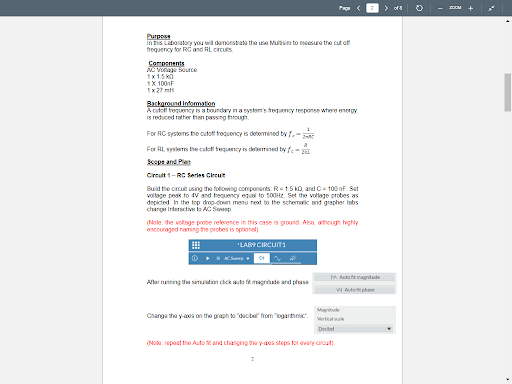
in this Laboratory you will demonstrate the store the cute frequency RC and RL CRES Components A vonage Source 1 x 15 1 X 100F Background information A tuto roccy is a totay in a systems frogany response when nergy is reduced rather than using through For HC systems the cuto troquency is determined by For All the corected by f. Cireult 1 - RC Series Greur Build the circuit using the following components: R-15 Dard C-100 nF Su voltage peak to Vand trecuency equal to 50Hz Set the voltage robes as depicted. In the top drop-down menu rest to the schermo and grapher tabs changin Note: the voltage proberelerence in this case is ground Also though highly encouraged roming the probes is optional) LAB CIRCUIT In ut magnitude Albert Marting the situation de soft magrisse ad pese Change they axs on the graph to date from our we Dobel oporte At and changing the ya stop for every cout in this Laboratory you will demonstrate the store the cute frequency RC and RL CRES Components A vonage Source 1 x 15 1 X 100F Background information A tuto roccy is a totay in a systems frogany response when nergy is reduced rather than using through For HC systems the cuto troquency is determined by For All the corected by f. Cireult 1 - RC Series Greur Build the circuit using the following components: R-15 Dard C-100 nF Su voltage peak to Vand trecuency equal to 50Hz Set the voltage robes as depicted. In the top drop-down menu rest to the schermo and grapher tabs changin Note: the voltage proberelerence in this case is ground Also though highly encouraged roming the probes is optional) LAB CIRCUIT In ut magnitude Albert Marting the situation de soft magrisse ad pese Change they axs on the graph to date from our we Dobel oporte At and changing the ya stop for every coutStep by Step Solution
There are 3 Steps involved in it
Step: 1

Get Instant Access to Expert-Tailored Solutions
See step-by-step solutions with expert insights and AI powered tools for academic success
Step: 2

Step: 3

Ace Your Homework with AI
Get the answers you need in no time with our AI-driven, step-by-step assistance
Get Started


