Answered step by step
Verified Expert Solution
Question
1 Approved Answer
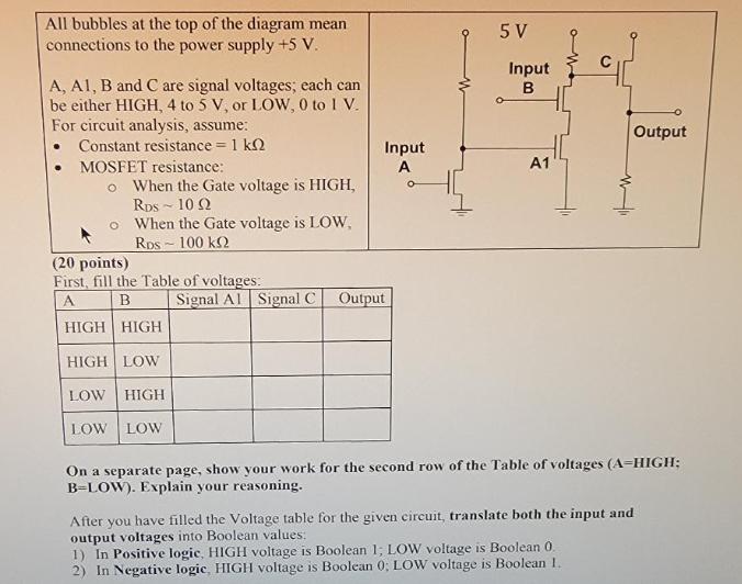
All bubbles at the top of the diagram mean connections to the power supply +5 V. A, A1, B and C are signal voltages;


All bubbles at the top of the diagram mean connections to the power supply +5 V. A, A1, B and C are signal voltages; each can be either HIGH, 4 to 5 V, or LOW, 0 to I V. For circuit analysis, assume: Constant resistance = 1 k MOSFET resistance: O When the Gate voltage is HIGH, RDS 10 Q2 o When the Gate voltage is LOW, RDS-100 k (20 points) First, fill the Table of voltages. A B HIGH HIGH HIGH LOW LOW HIGH LOW LOW Input A O Signal A Signal C Output 5 V Input B A1 Output On a separate page, show your work for the second row of the Table of voltages (A-HIGH; B-LOW). Explain your reasoning. After you have filled the Voltage table for the given circuit, translate both the input and output voltages into Boolean values: 1) In Positive logic, HIGH voltage is Boolean 1; LOW voltage is Boolean 0. 2) In Negative logic, HIGH voltage is Boolean 0; LOW voltage is Boolean 1. As a result of this translation, fill two Truth tables. 1. For Positive logic (20 points) ABOUTPUT 1 1 1 0 0 1 0 0 2. For Negative logic (40 points) A B OUTPUT 1 1 1 0 0 1 0 0 Show your work for the 3rd row of each Truth table (A-0; B-1). Explain your reasoning.
Step by Step Solution
★★★★★
3.50 Rating (160 Votes )
There are 3 Steps involved in it
Step: 1
To fill out the table of voltages and the truth tables we need to analyze the given circuit with respect to the inputs A B and C Looking at the circui...
Get Instant Access to Expert-Tailored Solutions
See step-by-step solutions with expert insights and AI powered tools for academic success
Step: 2

Step: 3

Ace Your Homework with AI
Get the answers you need in no time with our AI-driven, step-by-step assistance
Get Started


